Written by Akshay Dorle
Friday, July 03, 2026
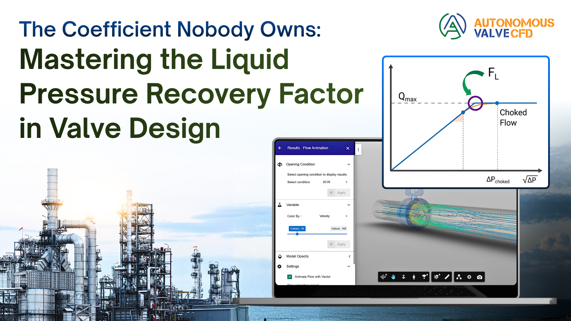
The Coefficient Nobody Owns: Mastering the Liquid Pressure Recovery Factor
By
Akshay Dorle

The number nobody double-checks
Standards define the Liquid Pressure Recovery Factor, FL. Sizing software runs on it to predict cavitation. Selection guides have warned about it for decades. But there's a quieter problem underneath all of that: everyone uses FL, and no one actually owns it.
The OEM quotes a catalog FL value. It came from loop-testing one representative valve, at full open, not the trim actually being shipped. The end user takes it on faith. The EPC specs to a standard and assumes the margin holds.
Nobody in that chain checks whether the catalog number matches the actual trim, at the actual opening, in the actual service. When it doesn't, the bill arrives later as cavitation: eroded trim, valves pulled mid-run, noise complaints, filed under maintenance and warranty rather than under FL.
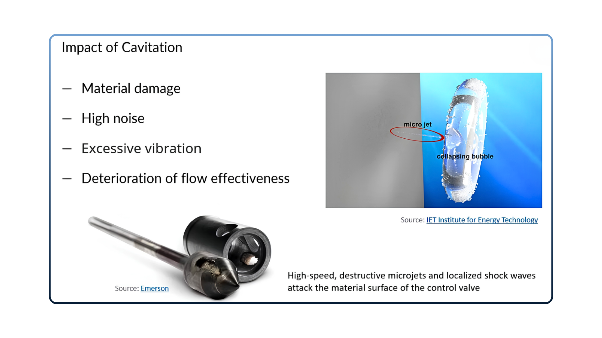
What cavitation actually does to a valve, over time.
Why Cv doesn't tell you this
Cv answers one question: can the valve pass the Flow? For most service, that's enough. But two valves with the same Cv can behave completely differently once pressure drop climbs, because they recover pressure differently.
As fluid accelerates through the trim, pressure falls to its minimum at the vena contracta, then partially recovers downstream. FL is what sets ΔPchoked, the pressure drop at which that minimum crosses the liquid's vapor pressure and Flow chokes:

A high FL pushes Δchoked higher, so the valve tolerates a bigger pressure drop before cavitating. A low FL means choking, and cavitation, starts at a much smaller ΔPchoked. A streamlined valve, like a ball or butterfly, tends to run low: it recovers pressure efficiently downstream, but that recovery comes from a sharper local dip at the vena contracta. A globe with a tortuous trim runs closer to 1, precisely because it doesn't recover much, so the local dip is milder relative to the total drop.
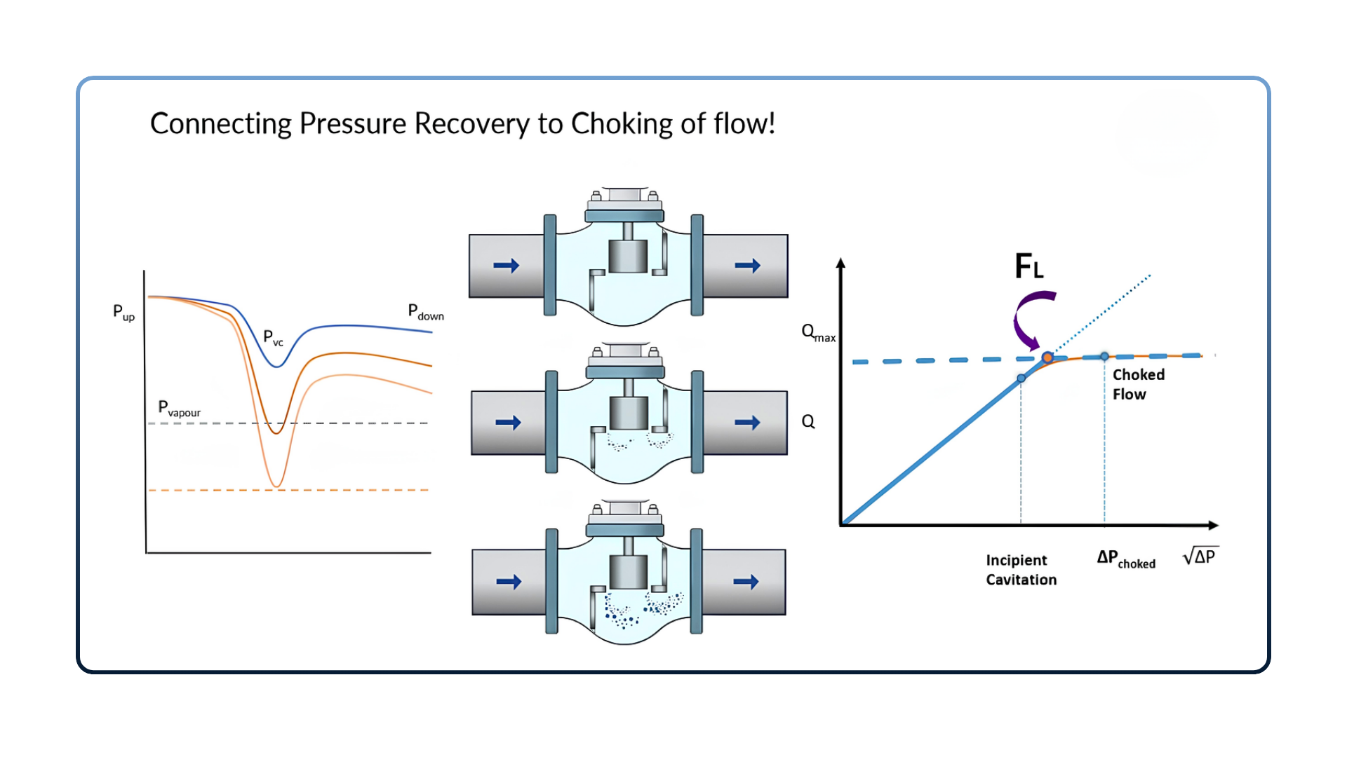
Pressure recovery, vapor formation, and the resulting FLow curve, for the same valve.
It follows a simple rule: σchoked ≈ 1/FL2.
Downstream, each collapsing vapor bubble fires a tiny jet of liquid at the metal. Millions of these per second, over months, erode the trim. That's the mechanism behind almost every valve failure that gets blamed on “wear and tear” instead of on the number that predicted it.
Cavitation isn't the only calculation that depends on FL
It's the most visible consequence, but standards use FL as a direct input to two other calculations:
- Noise. Once flow chokes, turbulence and bubble collapse radiate broadband noise that climbs sharply with pressure drop. IEC 60534-8-4 uses FL as a direct input to predicted sound pressure level at the pipe wall. Get FL wrong and the noise prediction is wrong too, sometimes enough to miss a site noise limit that only gets caught after commissioning.
- Choked-Flow capacity. Past the choke point, raising the pressure drop further doesn't raise the Flow. If FL is off, the valve is sized against the wrong ceiling, and the mismatch only shows up when the system can't hit its setpoint.
Your datasheet's FL isn't your valve's FL
FL belongs to a specific geometry: trim profile, cage porting, seat, disc, and the exact opening. It even shifts across the stroke. The datasheet treats it as a fixed label instead: globe 0.9, butterfly 0.6, ball low. Add a cage, a triple-offset disc, or run the trim at 40 percent open, and that number stops describing your valve.
Installation adds another layer on top of that. A reducer, an elbow, or a short straight run upstream of the valve changes the velocity profile arriving at the trim, which is exactly what the catalog test didn't have. That's why engineers who stay well below the published FL limit still end up with cavitation damage: the number they trusted was measured in a condition their installation doesn't match.
“My sizing software already handles this”
Every major manufacturer's software flags cavitation risk and steers toward anti-cavitation trim, following ISA/IEC guidelines. But under the hood, that software runs on catalog FL values and family-level correlations. It's a guide built on general data for the valve family, not a measurement of the specific valve on the line.
Three ways to actually get FL
- Measure it. Flow-loop testing under ANSI/ISA-75.02.01 is ground truth. It's also slow, expensive, and limited to sizes that fit the rig. A handful of tested valves become the catalog numbers everyone else inherits.
- Compute it with conventional CFD. In theory this gives you FL for any trim at any opening. In practice, cavitation is a phase-change problem: a careful mesh, a multiphase solver, and days of specialist setup per study. It usually only happens after a valve has already failed.
- Compute it with Autonomous Valve CFD. Same number, straight from the valve's 3D model, as a same-day answer instead of a multi-day study.
Put a real number on the datasheet
Run AVC on a design and the gap between the catalog number and reality shows up quickly. A globe valve swept from 25 to 100 percent open holds FL between about 0.86 and 0.87 on its own; add a single-stage cage and it climbs to about 0.95, moving the safe cavitation threshold with it. A same-Cv globe and butterfly that look interchangeable on a sizing calculator split just as clearly, FL near 0.86 for one and about 0.76 for the other wide open, which is the difference between a valve that survives high-pressure-drop service and one that doesn't.
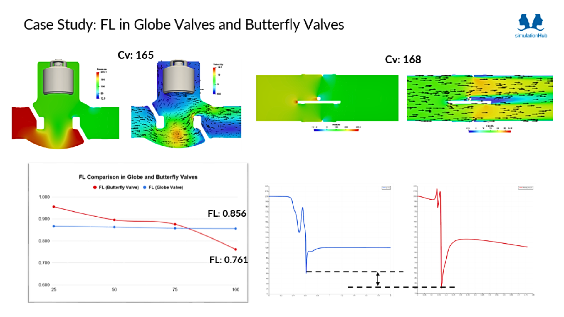
Globe vs. butterfly, same Cv, different FL across the stroke. Source: AVC.
These are the kinds of differences a catalog number was never built to catch, and a full CFD study normally takes a specialist days to produce for one pair of valves. AVC reaches the same numbers directly from the 3D model, as a same-day answer, on any trim, any opening, cage or no cage. The OEM can put an actual FL curve on the datasheet. The end user can verify a vendor's claim before it ships. The EPC can require a geometry-specific recovery curve, the same way it would require a pressure rating.
See Your Valve's Real FL
For high-pressure-drop liquid service, the Cv on a spec sheet is rarely the question that matters. FL is: what it actually is for this valve, at the opening it will run, and who computed it. A handbook average means inheriting someone else's decades-old loop test and hoping the service matches. Three parties can act on a real FL curve instead of a guess: the OEM designing the trim, the end user specifying the service, and the EPC writing the standard into the contract. AVC gives all three the same number to work from.
Before the next spec goes out, it's worth asking three questions of whatever FL value is already on the datasheet:
- Is this value for the exact trim being shipped, or for the family it belongs to?
- Is it given across the stroke, or only at wide open?
- Was it measured on this geometry, or carried over from an older design?
If any answer is uncertain, that's the gap AVC is built to close: certified Cv, Kv, and Cdt data, FL included, in under 30 minutes on your own CAD file. The first simulation is free, on your actual design, full feature access for 15 days, no credit card.
Understand FL with Autonomous Valve CFD
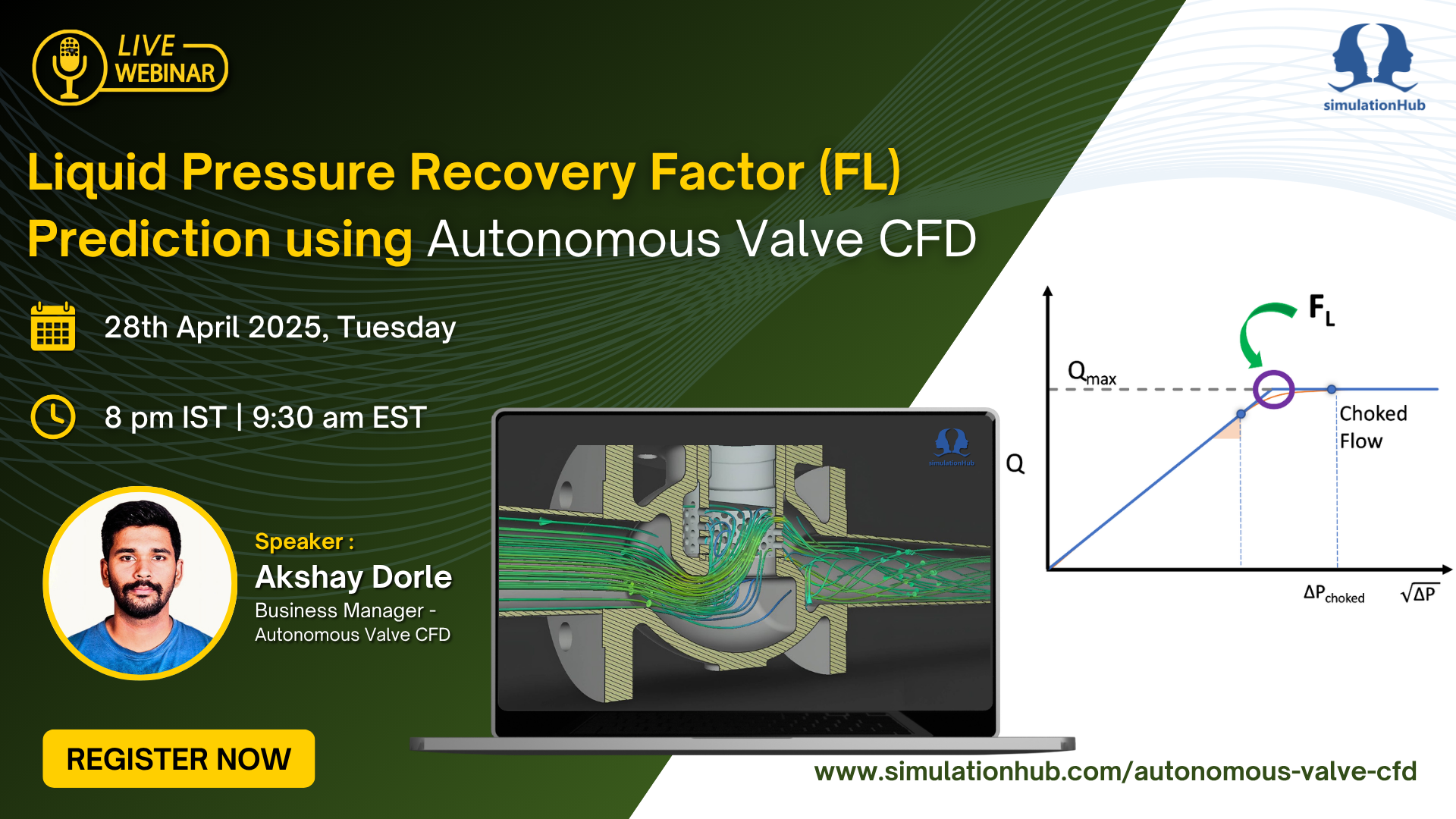
If you'd like a deeper look at how Liquid Pressure Recovery Factor (FL) is calculated, why it varies with valve geometry and opening, and how autonomous CFD can generate certified FL predictions directly from your valve design, watch our on-demand webinar: "Liquid Pressure Recovery Factor (FL) Prediction Using Autonomous Valve CFD."
Watch the Webinar
If you're ready to go beyond handbook values, explore Autonomous Valve CFD (AVC) and see how it generates certified Cv, Kv, Cdt, and FL data directly from your CAD model - in under 30 minutes. Or schedule a guided walkthrough with our engineering team to see how AVC can fit into your valve design and validation workflow.
See What's New in AVC
Book a Free Demo
Comments
Recent posts