Written by Karan Beeshm
Sunday, August 02, 2026
Simulating Ice Thermal Storage Systems Using BuildingsAI - Part 2: A Chicago Apartment Case Study
By
Karan Beeshm

New to This Series? Start with Blog 1
Missed it? Check out the companion post first: "Inside the Model: How Ice Thermal Storage Systems Actually Work." It walks through the underlying mechanics — how the ice tank interacts with the chiller, what "charging" and "discharging" mean at the equipment level, and why the time-of-day supply temperature schedule is the key control lever — before this post puts those mechanics to the test in a real Chicago building.
Part 01 : How Ice Thermal Storage Systems Actually Work
Putting the Model to the Test
Ice thermal storage systems let a building "pre-cool" itself overnight — freezing water into ice during cheap, off-peak hours, then melting that ice during the day to help meet cooling demand without running the chiller as hard. It's an appealing idea on paper. But does it actually move the needle on cost and comfort in a real building?
To find out, we simulated a full year of operation for a mid-rise residential apartment building in Chicago, using BuildingsAI's detailed ice storage and VAV reheat models. Here's what the numbers showed.
The Building and the Climate
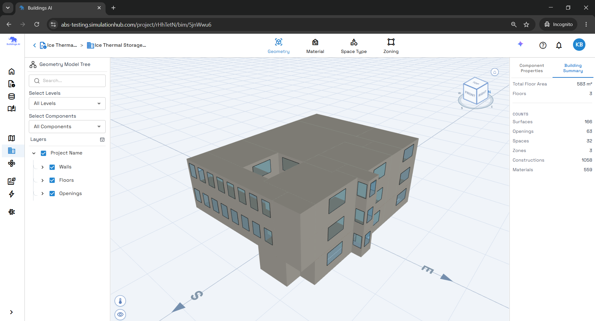
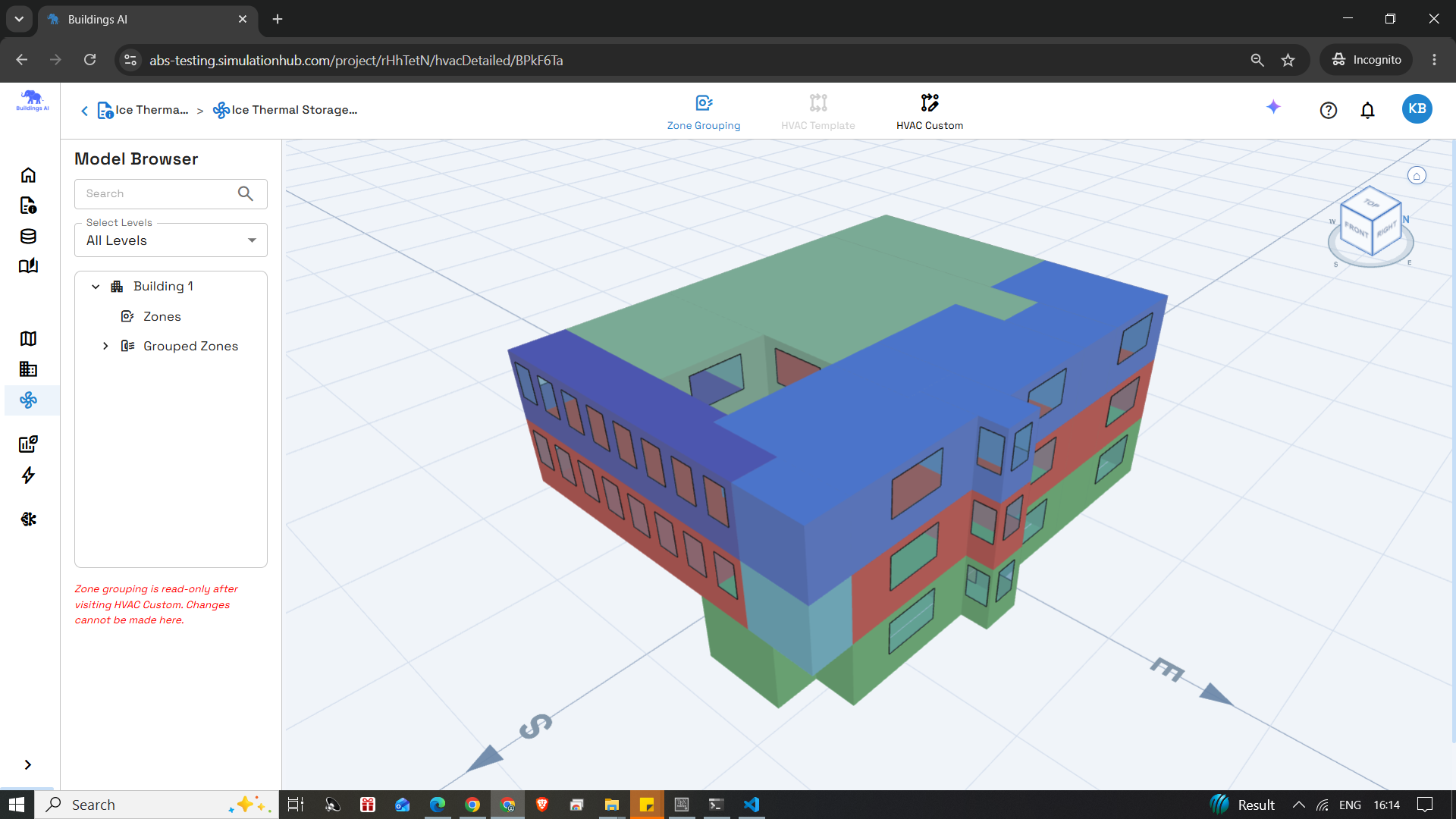
The case study models a mid-rise apartment prototype with seven conditioned thermal zones spread across the building footprint, each served by its own variable-air-volume (VAV) terminal drawing from a shared central air system. Occupancy, lighting, plug loads, and ventilation follow the ASHRAE 90.1 Mid-rise Apartment prototype assumptions — so the loads reflect realistic residential behavior, not a simplified test case.
The cooling plant pairs a water-cooled electric chiller in series with a detailed ice storage tank. During off-peak hours, the chiller charges the tank; during occupied hours, the discharging ice supplements the chilled-water loop. Heating comes from a natural-gas-fired hot-water boiler serving reheat coils at each VAV terminal.
We chose a demanding climate on purpose: Chicago O'Hare International Airport (41.98° N, -87.92° W), a cold, heating-dominated location with a short but intense cooling season. Design days used for equipment sizing were the 0.4% annual cooling design day (37.2°C max dry-bulb / 25.5°C wet-bulb) and the 99.6% annual heating design day (-20°C dry-bulb) — a wide seasonal swing that stress-tests both the ice storage charge/discharge cycle and the hot-water reheat system simultaneously.
The envelope itself is solidly built to prototype standards: an insulated metal roof (R-31.25), steel-framed exterior walls (R-15.63), and an insulated exterior mass floor (R-19.61), combined with exposed concrete floor and ceiling slabs that add real thermal mass throughout the building. Low-U, low-SHGC glazing (U-2.16, SHGC 0.35 on the main façade) keeps solar and conductive gains in check without sacrificing daylight.
How the System Was Configured
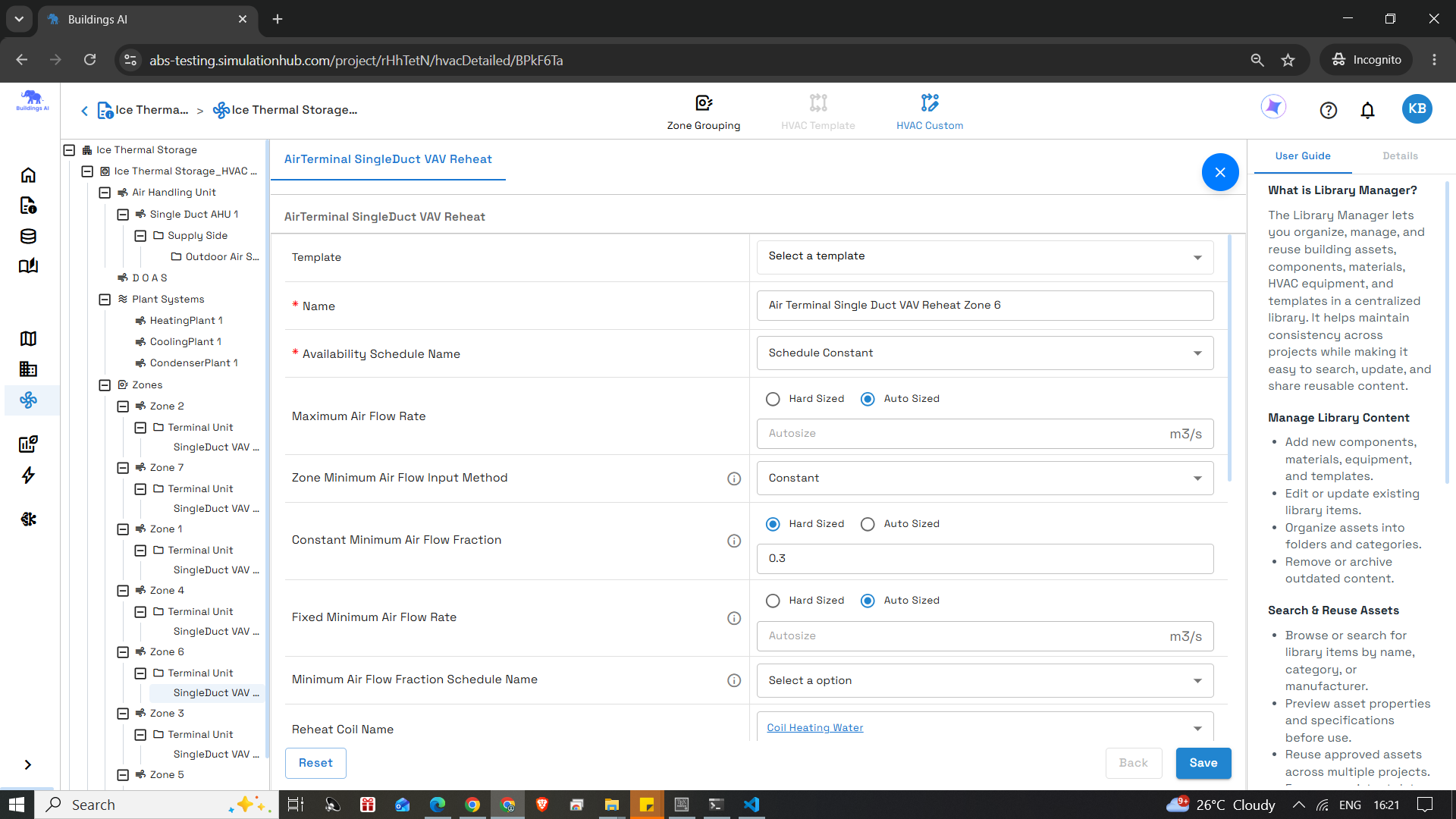
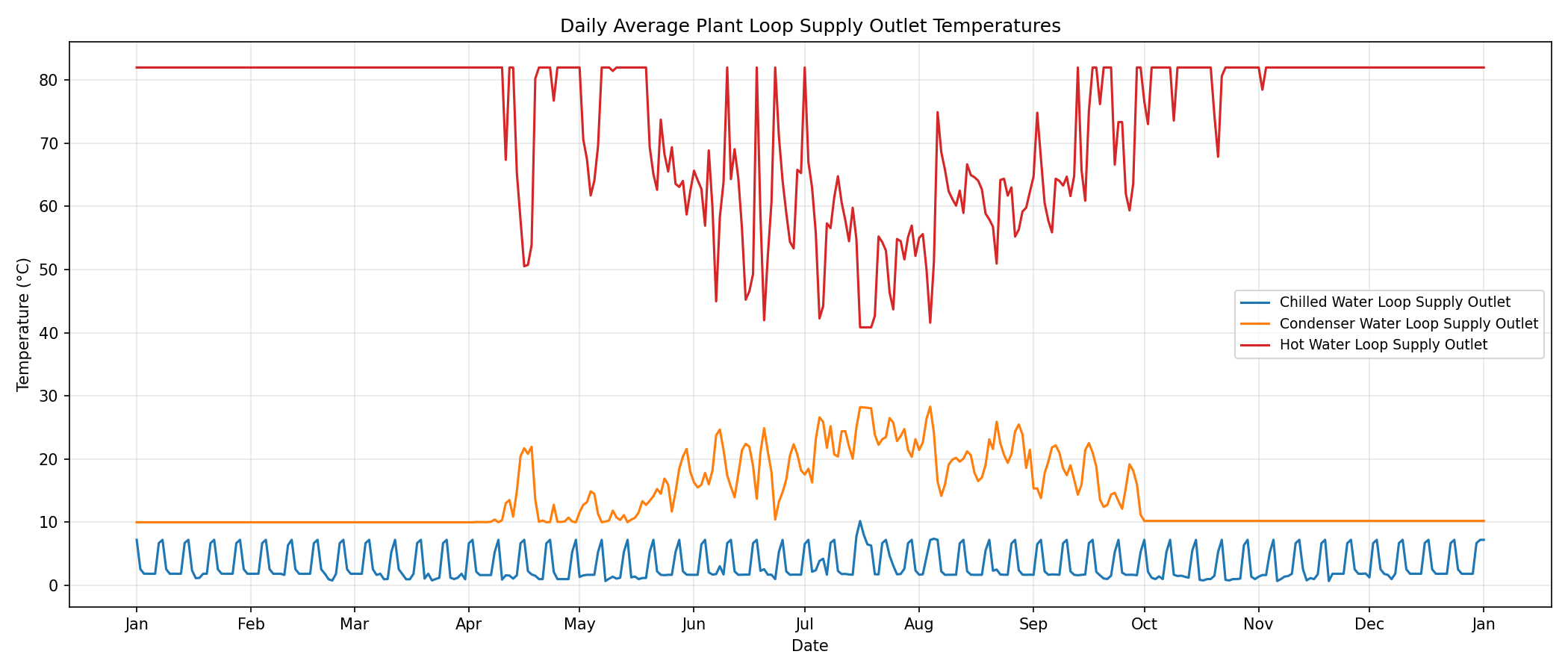
The central plant ties together six major pieces of equipment: a constant-speed chilled-water pump, variable-speed condenser-water and hot-water pumps, a natural-gas boiler, a water-cooled electric chiller, the detailed ice storage tank, and a single-speed cooling tower.
A few control details matter here:
- The chiller runs at a reference capacity of 22.5 kW and a reference COP of 3.2, with performance evaluated against water-cooled curves as a function of leaving chilled-water temperature and entering condenser fluid temperature.
- The ice tank sits in series with the chiller on the chilled-water supply side. A time-of-day supply temperature schedule drives the behavior: roughly −5.0°C during charging hours, and 7.22°C otherwise — that's the signal that tells the plant when to freeze and when to just deliver normal chilled water.
- The boiler is sized at 58.1 kW with a nominal thermal efficiency of 0.8, modulating hot-water flow to hold the leaving water temperature the VAV reheat coils need.
- The cooling tower tracks outdoor wet-bulb temperature to reject condenser heat.
Comfort Held Up — Everywhere
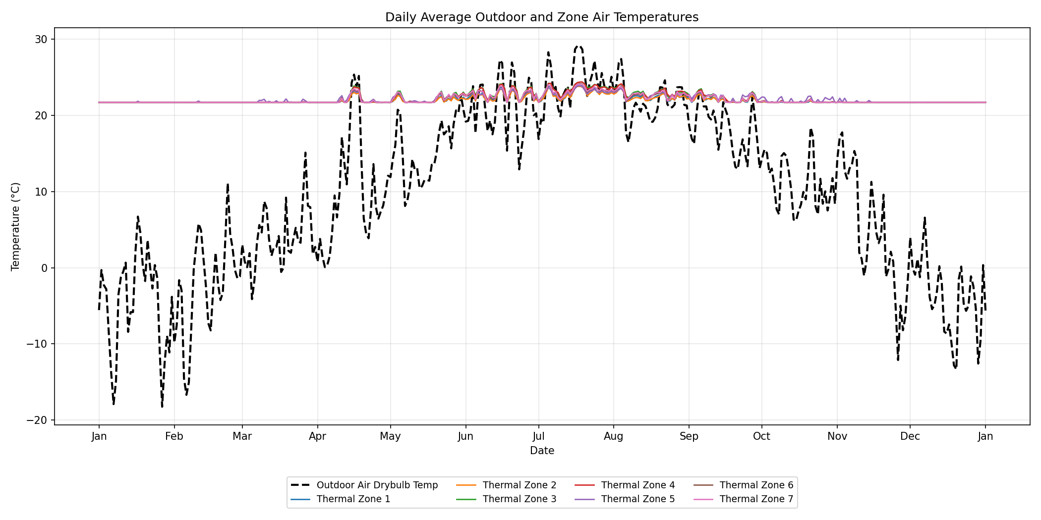
Before looking at cost, it's worth confirming the system actually did its job. Across all seven zones, for all 8,760 hours of the year:
- 100% of hours stayed in the “safe” heat-index band (below 26.7◦C) — zero caution, danger, or extreme-danger hours anywhere.
- 95.3% of hours fell in the "little to no discomfort" humidex band, with the remaining hours landing in "some discomfort" — no zone ever reached "great discomfort."
- Cooling setpoint tracking was nearly perfect: unmet cooling degree-hours ranged from 0.00 to just 0.13 °C·hr per zone across the entire year.
- Heating setpoint tracking was also strong, with modest unmet degree-hours (2.16–5.64 °C·hr per zone, 24.76 °C·hr total) consistent with brief reheat-coil lag during the coldest design conditions.
In other words: the ice-storage-assisted plant wasn't trading comfort for cost savings. It held setpoints tightly across a genuinely harsh climate swing.
Where the Savings Actually Come From
This is the part that matters most for anyone evaluating ROI. The simulation tracked electricity consumption separately for on-peak and off-peak hours. (3,380 on-peak hours/year, 5,380 off-peak hours/year):

Notice the chiller pulls a larger off-peak share (64.3%) than the facility average (59.0%). That gap is the ice storage system doing exactly what it's designed to do — shifting the chiller's heaviest work into the cheap, off-peak charging window.
Applying a Chicago (ComEd) time-of-use rate — $0.107/kWh on-peak, $0.040/kWh off-peak — that shift produces a real dollar impact:

That's an estimated ∼$1,135 annual reduction in chiller electricity cost — roughly 40% — driven almost entirely by moving load off-peak rather than reducing total energy use. The logic is straightforward: without storage, the chiller would have to run whenever the building needs cooling, which is disproportionately during expensive on-peak hours. With storage, most of that same cooling work gets done overnight instead.
One important caveat: this isn't a direct simulation-to-simulation comparison. The "without storage" figure is an engineering estimate based on shifting the chiller's existing annual consumption into an on-peak-heavy pattern, not a separate full-year simulation with the tank physically removed from the plant. A rigorous baseline would run that second simulation explicitly. Directionally, though, the result lines up with how utilities structure time-of-use pricing in the first place — and it's a meaningful enough estimate to justify running that baseline case if you're evaluating this for a real project.
The Takeaway
In a cold-climate building where cooling season is short but intense, ice thermal storage still delivered a substantial estimated cost benefit — without compromising comfort or setpoint tracking. The mechanism is simple and verifiable in the data: shift the chiller's electrical load into off-peak hours, and let the utility rate structure do the rest.
If you're evaluating whether ice storage makes sense for a specific building, the two things worth checking early are (1) how wide the gap is between your on-peak and off-peak utility rates, and (2) whether your cooling load profile actually aligns with a practical overnight charging window. Both of those were favorable in this case study — and the results reflect it.
In a cold-climate building where cooling season is short but intense, ice thermal storage still delivered a substantial estimated cost benefit — without compromising comfort or setpoint tracking. The mechanism is simple and verifiable in the data: shift the chiller's electrical load into off-peak hours, and let the utility rate structure do the rest.
Take the Next Step: Start Your Free Trial or Book a Demo
Comments
Recent posts
Message
Dummy Name
Subscribe Newsletter
Register for Webinar
Sign up for AHC
App Dashboard
Buildings AI
Maximize building performance and path towards NZEB with our cloud-based, AI powered whole building performance modeling software.

Autonomous Valve CFD
Get CV, KV performance curves within minutes for your valve design. An automated CFD simulation based app for control valve designers.

Autonomous HVAC CFD
Leverage the power of autonomous HVAC CFD to design an efficient HVAC system for achieving indoor air quality and occupant thermal comfort.