Written by Angirekula Venu
Wednesday, October 21, 2026
Why Two Identical Fabric Ducts Can Need Very Different Fan Static
By
Angirekula Venu

It shows up at commissioning. The fan is running and the duct is inflated, yet the balancing readings come up short — less airflow than design, and fabric that hangs slightly slack. Nothing about the duct looks wrong.
Sometimes the duct itself is fine. The whole duct is running below the pressure it needs, because the fan was selected for the wrong static pressure.
Behind that number sits one input most people take it lightly: how cleanly air leaves each perforation.
What happens at a perforation
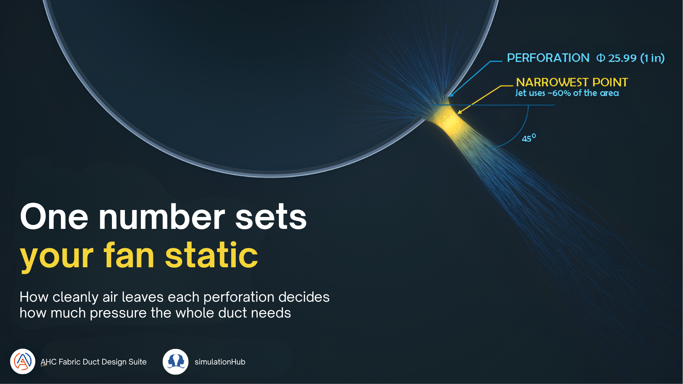
Air inside the duct reaches each perforation from every direction, including sideways along the fabric. It cannot turn sharply at the edge, so the jet keeps narrowing for a short distance after it leaves. Behind a clean, sharp edge, the jet at its narrowest uses only about 60% of the perforation's area.
Commercial buildings felt the heat directly. In Saint-Denis, workers described offices that offered little relief - the outdoor heat simply followed them inside. That is no longer just a comfort issue. Since July 1, 2025, French employers must assess heat-related workplace risk, verify that ventilation systems are effective, and adapt work organization when Météo-France yellow, orange, or red heat-vigilance thresholds are reached. Comfort guidance already sets a narrow target: NF X35-203 / ISO 7730 points to 20-22°C, while INRS allows a practical summer range of 23-26°C. During sustained heatwaves, naturally ventilated or under-sized commercial spaces can quickly move beyond both bands, increasing discomfort, productivity loss, and safety risk.
The pattern is consistent: commercial buildings that weren't designed - or verified - to hold their temperature and ventilation targets under sustained heat stop functioning as usable workspace, regardless of whether cooling equipment is technically present.
Remedies and Indoor Comfort: What's Being Done, and What's Missing
Regulation has moved faster than most building infrastructure. Employers are now required to run heat-risk assessments, adapt to work organization, and confirm their ventilation systems perform - but "confirm ventilation performs" is exactly where most commercial buildings run out of tools. Checking that an AHU is running isn't the same as knowing whether conditioned air reaches every desk.
Engineers capture this with one number, the discharge coefficient (Cd): the share of a perforation's ideal airflow that it actually delivers. A clean, sharp-edged perforation has a Cd of about 0.60. Change the edge, and Cd changes with it.
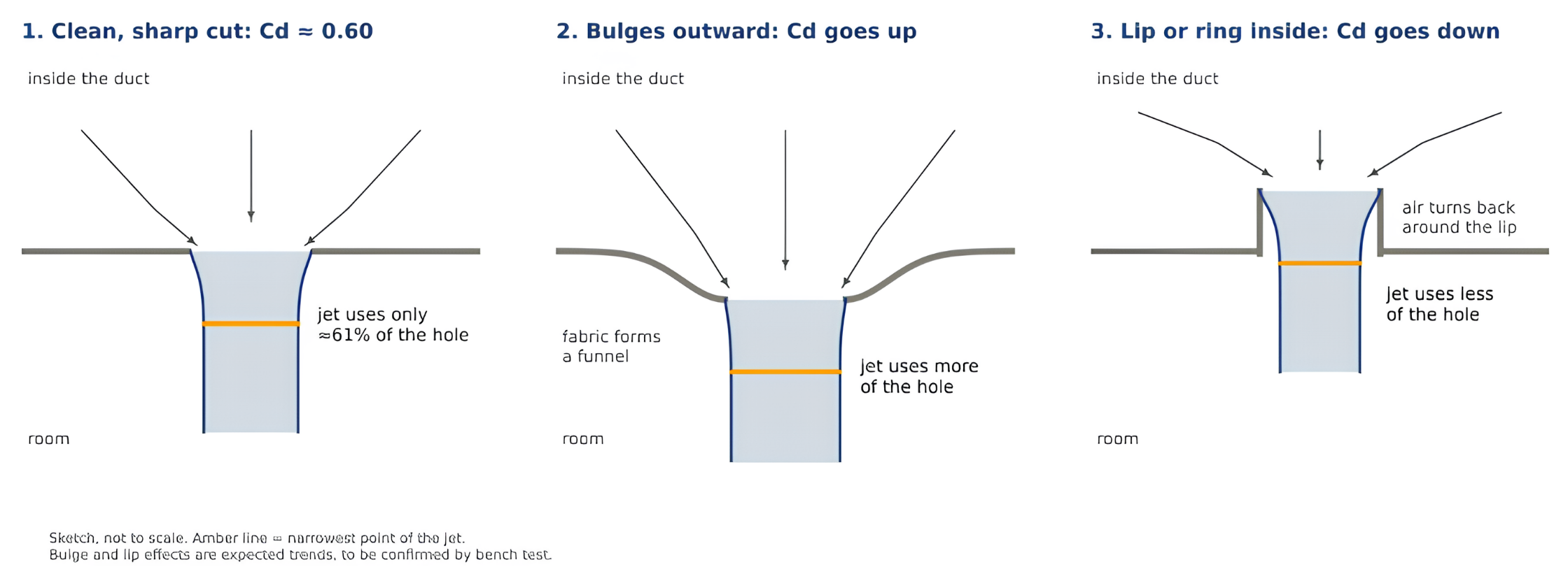
Same perforations, three edges. The edge decides how much of the perforation the jet actually uses.
We simulated one fabric duct, with the room around it, in full 3D using CFD (Computational Fluid Dynamics) to find out how much that input matters. Our 3D model shows exactly this on the fabric. Taking the local duct static at each perforation and averaging over all 94, it gave a Cd of 0.594 for a clean edge, right where classic hydraulics puts a sharp-edged perforation’s discharge coefficient.
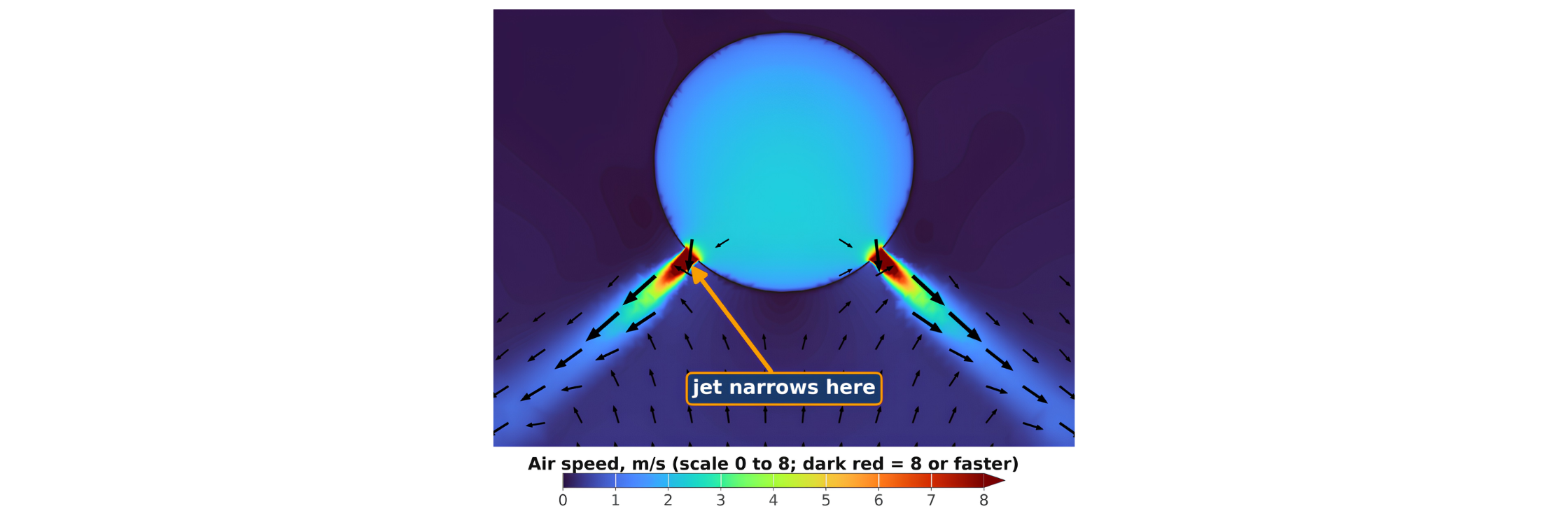
The jet pinches just outside the fabric, then spreads into the room. The colour scale here runs from 0 to 14 m/s (0 to 2,760 fpm), so the jet core at its narrowest point stays in range.
One duct, 10 million cells
The duct was 14 in (356 mm) round and 40 ft (12.2 m) long, with an end cap. It carried 750 CFM (354 L/s) through 94 perforations of 25.9 mm (about 1 in), in two rows angled 45° below horizontal.
We modelled the duct and its room together: 13.1 × 4.0 m (43 × 13 ft), 3.7 m (12 ft) high, with about 10 million cells, as a steady-state RANS simulation with a mass-flow inlet and the room at ambient pressure. Each jet could form, narrow and spread in real room air, as it does on site. The fabric was modelled as non-permeable, so all the air leaves through the perforations.
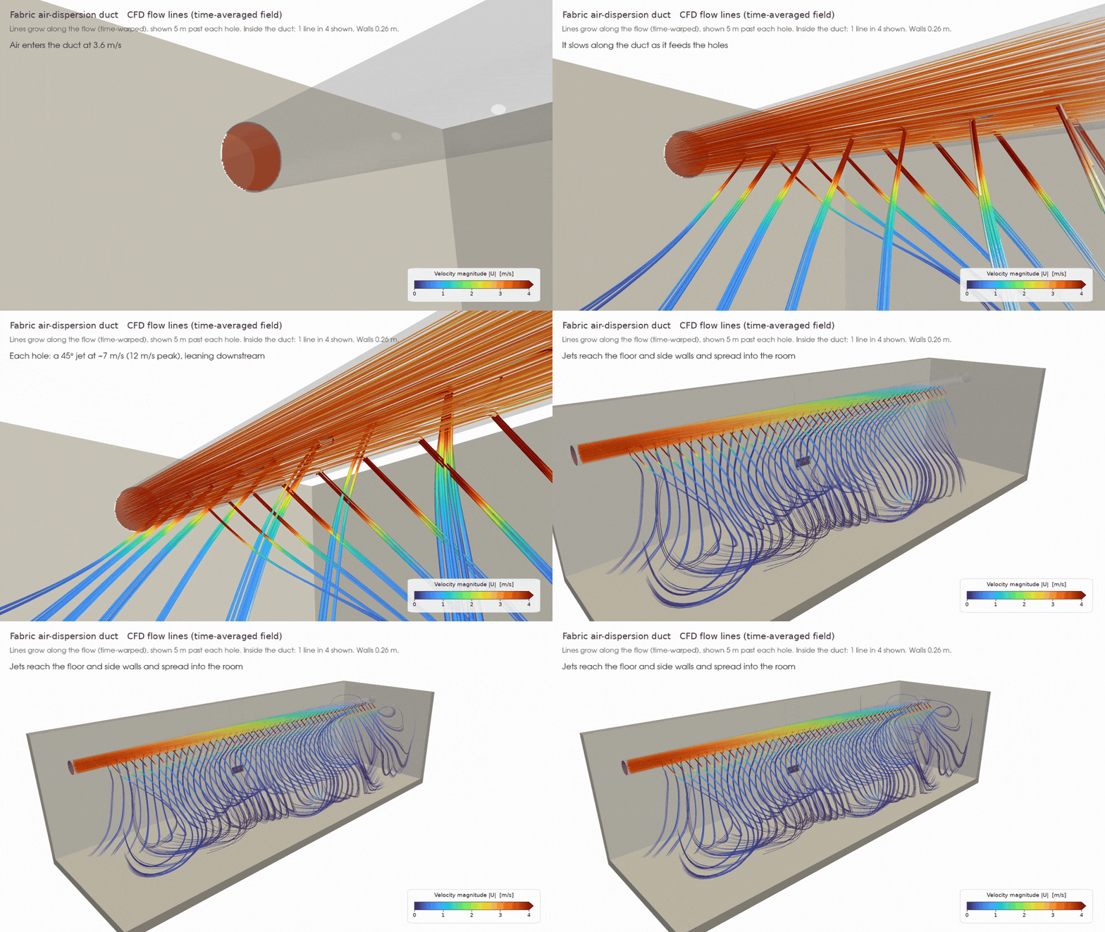
Air enters at the left and leaves through the perforations. The colour scale runs from 0 to 4 m/s (0 to 790 fpm).
Entire design, single click
Duct Validator in AHC Fabric Duct Design Suite, a physics solver that runs in minutes by walking along the duct piece by piece, tracking friction, the pressure that builds as the air slows, and the flow through every perforation. It takes fabric permeability as a separate input: permeable fabric adds a second, parallel path for air, while Cd still sets how much the perforations pass at a given static.
Set to that same Cd of 0.594 in AHC Fabric’s Duct Validator gives 82.9 Pa (0.33 in. w.g.) at the duct inlet, against 83.1 Pa from the 3D CFD.
One number, a 2.7× swing in fan static
Same duct, same 750 CFM, same perforation layout. Only Cd changes:
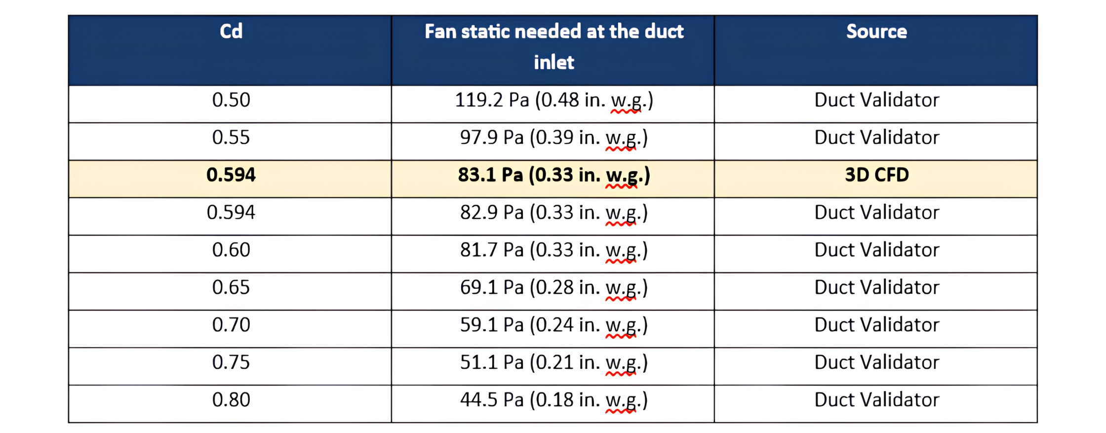
Static is measured at the duct inlet, relative to the room. The fan also has to cover the AHU and the supply ductwork. All Duct Validator values use its default settings.
From 0.80 to 0.50, the fan static rises 2.7×. The rule behind it is simple: static goes with 1 over Cd squared. A 10% lower Cd needs about 23% more static. An error of just ±0.02 on 0.60 moves the fan static by about ±7%.
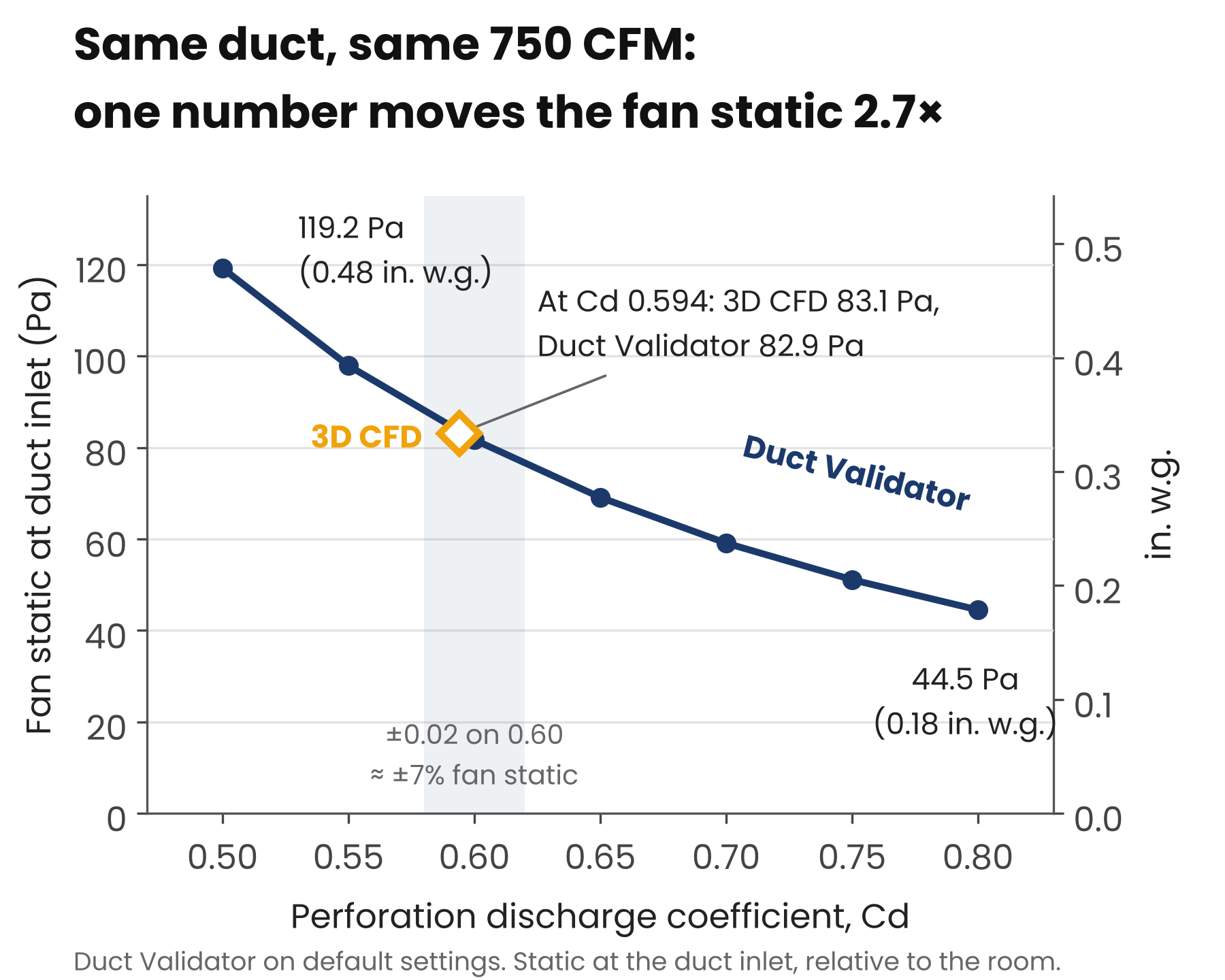
One input, a 2.7× swing in fan static. The 3D CFD lands at Cd 0.594.
Now picture a design done at 0.60 for perforations that really behave like 0.50 in real life. The duct needs 119.2 Pa (0.48 in. w.g.), not 81.7 Pa (0.33 in. w.g.). A fan selected for 81.7 Pa leaves every perforation short of air. The room runs short, and the fabric may not fully inflate. The error can run the other way too: a higher Cd lowers the static, so check it stays above the fabric maker’s minimum for full inflation.
Cd sets the level, not the shape. At every Cd, pressure rose by the same 5.7 Pa (0.023 in. w.g.) toward the end cap as the air slowed (static regain). That is why a wrong Cd starves every perforation, not just the last ones.
The cut is the fingerprint
Here is why two "identical" ducts can need different fans. Cd depends on how the perforation is made:
- Edge. Laser cut, punched or reinforced: each leaves a different edge, and so a different Cd. Only a test on your own fabric tells you which.
- Diameter tolerance. A perforation 5% oversize has about 10% more area. At the same airflow, the duct then needs about 18% less static. At the same static, it passes about 10% more air. Holding ±0.25 mm (±0.01 in) on a 25.9 mm perforation keeps the static within about ±4%.
- Fabric movement. Fabric that domes outward under pressure forms a small funnel and should push Cd up. A ring or lip on the inside should pull it down. These are expected directions, to be confirmed by a bench test by manufacturers.
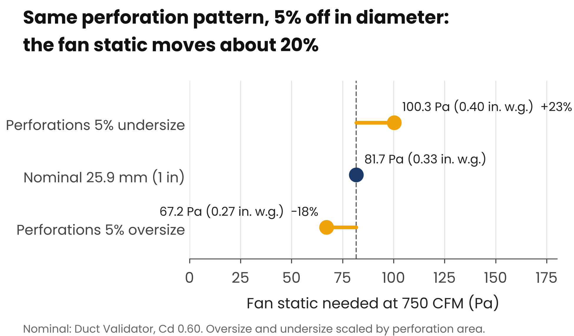
Same perforation pattern, different diameter, different fan. Duct Validator result for the nominal perforations; oversize and undersize cases scaled by perforation area.
Two manufacturers can ship the same perforation pattern and need different fan static to deliver the same airflow.
What it means for you
If you make fabric duct: your fabric, your cutter and your tolerance are your Cd. Measure it once on production fabric: a sealed plenum, a calibrated flow meter, several test pressures, and the fabric's own seepage subtracted. A plenum bench has no air sweeping past the perforations as it does inside a duct, so treat the bench value as your starting value. Then publish it with the product.
If you install it: measure the static at the duct inlet. If it is below the design value, raise the fan speed. If it matches the design value and the room is still short of air, the design value itself may be too low. Ask which Cd the design assumed and created for.
If you specify it: add one line to the spec: "Supplier shall state the perforation discharge coefficient used for fan static, and whether it was measured on production fabric or assumed."
Set your own Cd in the Duct Validator:
This is why we made the perforation discharge coefficient a single setting in AHC Fabric. In the Duct Validator's configuration panel, "Element Discharge Coeff (Kd)" is a slider — the same discharge coefficient (Cd) this article discusses, just labelled Kd in the tool. It starts at 0.60, the clean sharp-edge value, right beside the 0.594 our 3D model found.
If your bench test says your perforations run at 0.55 or 0.68, move the slider and run the validation. The fan static, the pressure along every duct and the airflow at every perforation update across the whole network, from your number, not a generic one.
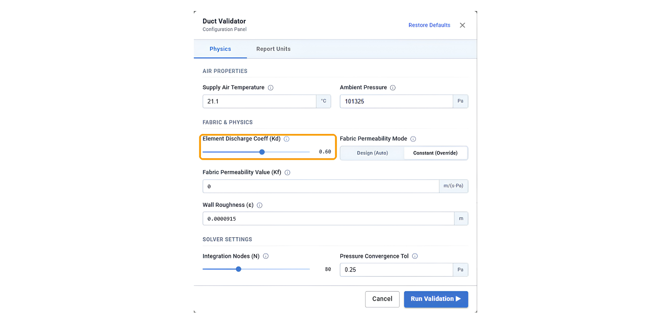
Your perforation discharge coefficient is one slider in the Duct Validator. Here fabric permeability (Kf) is set to 0 to match the non-permeable CFD.
Put your own Cd to work
Don't size a fan on a generic 0.60. Bench-test your production fabric, set the number in the Duct Validator, and see the fan static before anyone selects a fan.
Learn how AHC Fabric Duct Design Suite helps you validate fan static and airflow before installation, at simulationHub.
Explore Fabric Duct Design Suite
Book a Free Demo
Comments
Recent posts