Written by Angirekula Venu
Monday, June 01, 2026
Why Every Meter Matters - Pressure Distribution in Fabric Dispersion Ducts
By
Angirekula Venu
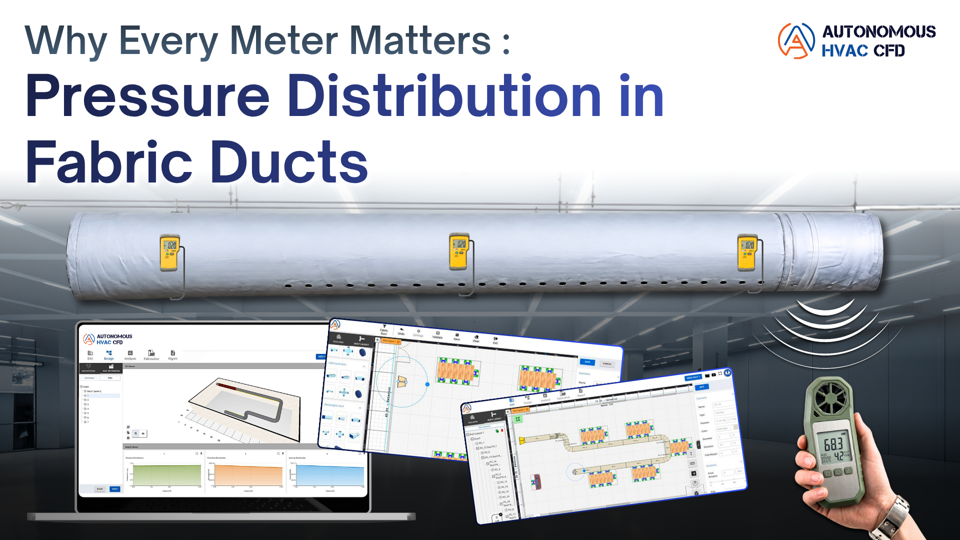

What Are Fabric Ducts?
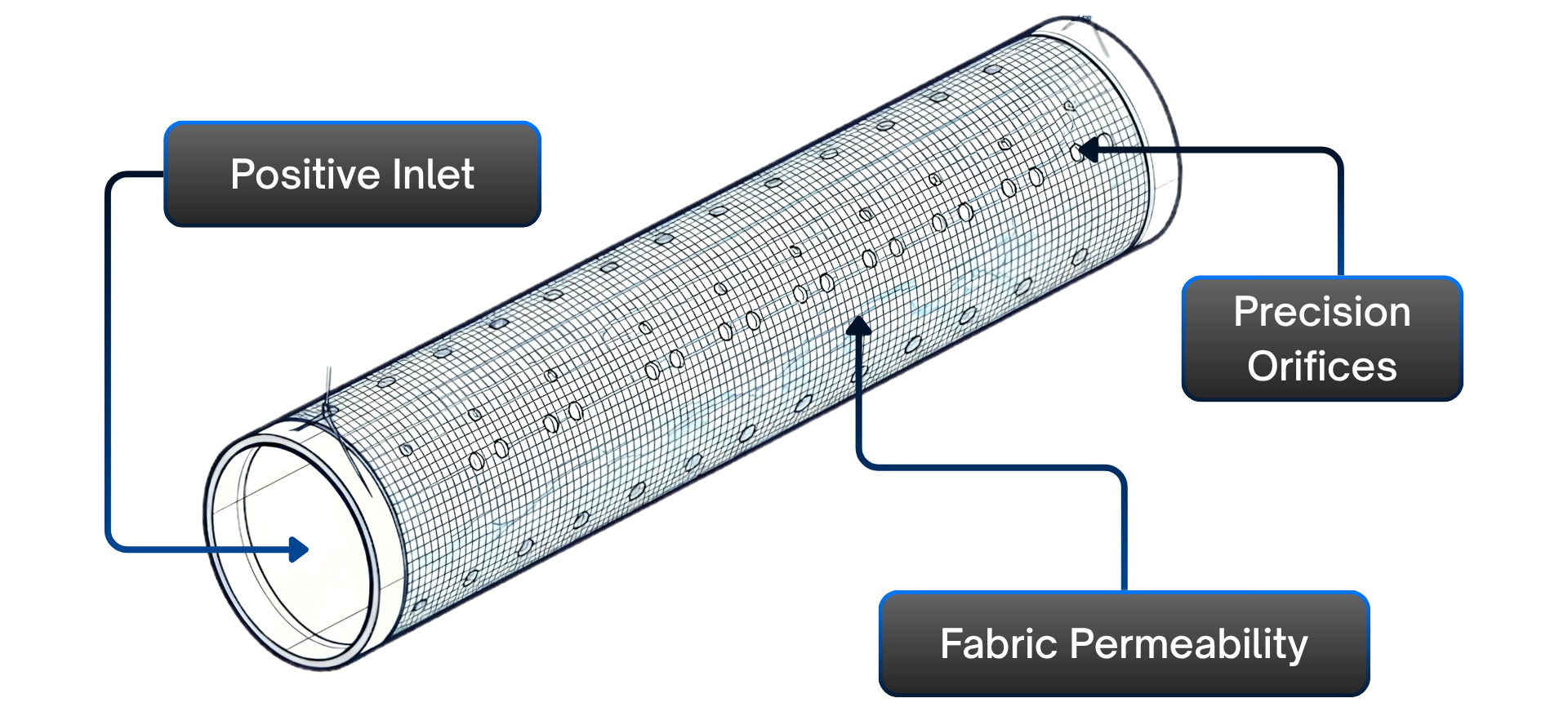
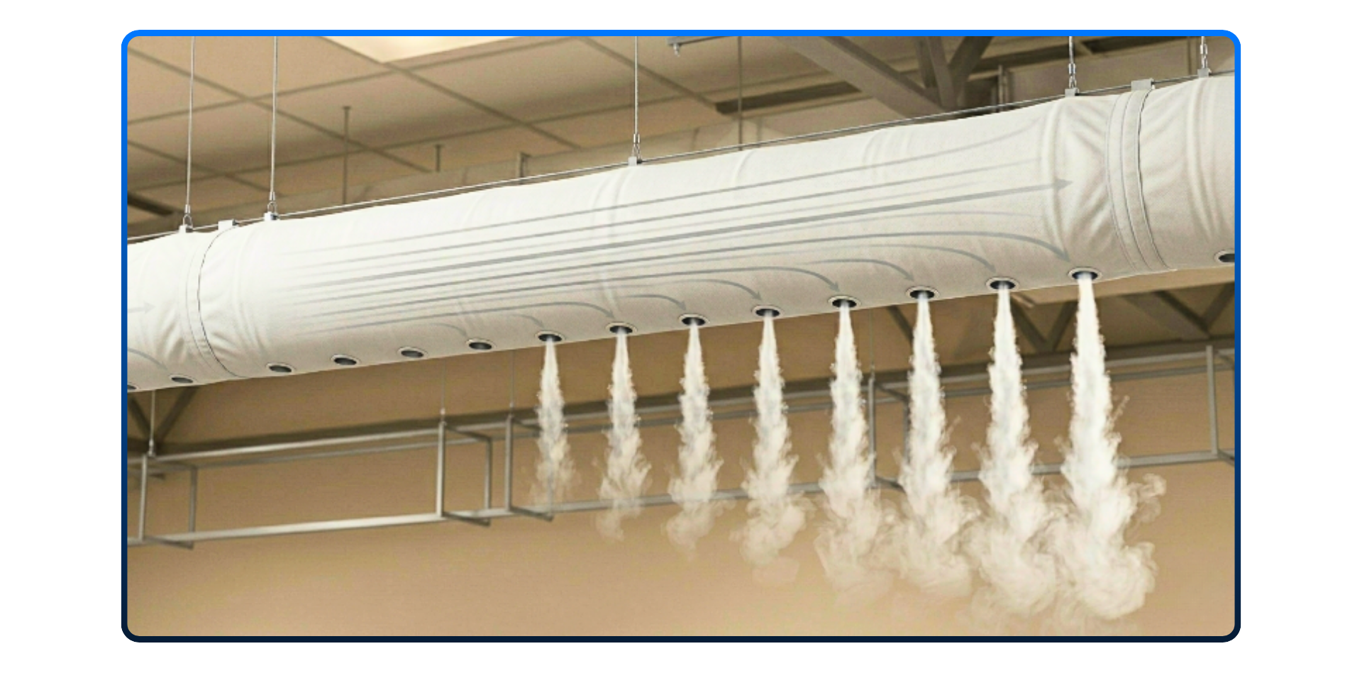
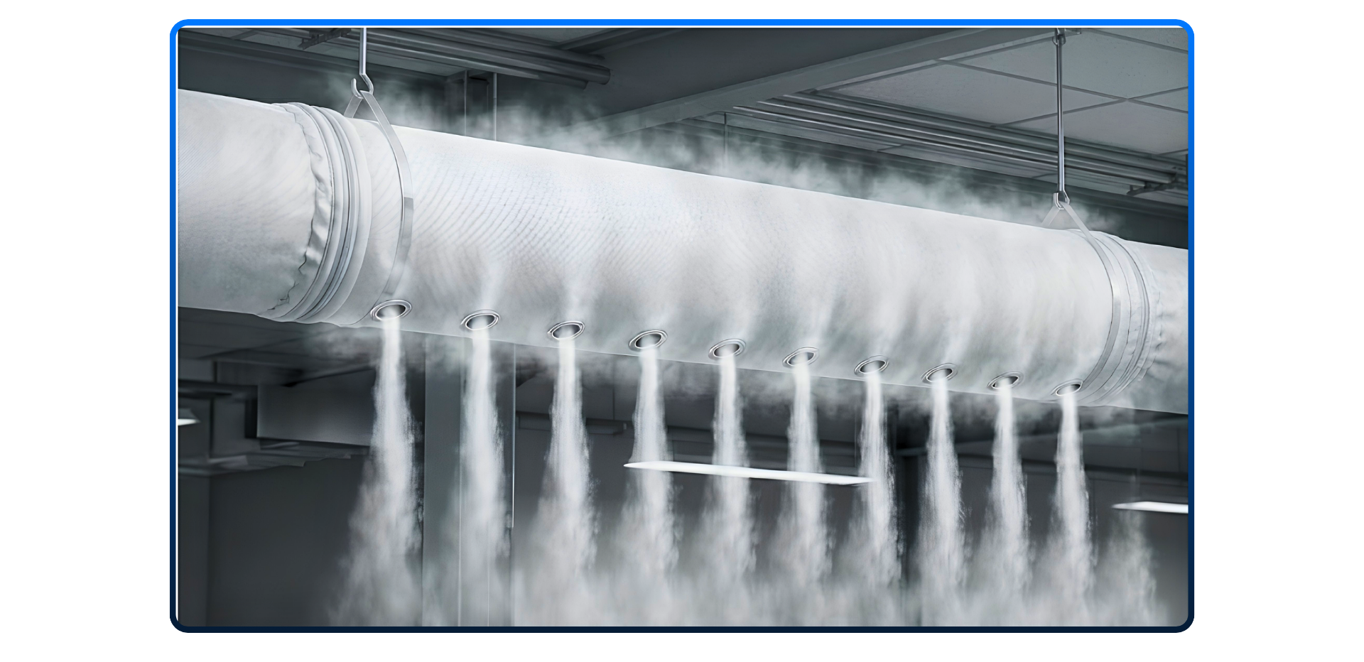
Fabric ducts are ducts made of special grade fabric material as an alternativity to conventional metal ducts. They offer many advantages and address the issues that come up with sheet metal ducts. Air enters at one end under positive static pressure and exits continuously through precision-positioned orifices punched or laser-cut into the fabric wall, and in some cases through the permeable weave of the fabric itself. There are no grilles, no branch diffusers, no terminal units. Therefore, this is simultaneously the duct and the distribution terminal.
Food-processing plants, cold stores, gymnasiums, warehouses, datacenter hot-aisles, and airport terminals all make use of this distribution system because it combines even, draught-free air delivery with light weight, rapid installation, and easy maintenance. The duct is suspended from overhead tracks or cables and can be demounted for machine-washing - a significant hygiene advantage in food and pharmaceutical environments.
The Core Challenge: Distributed Discharge
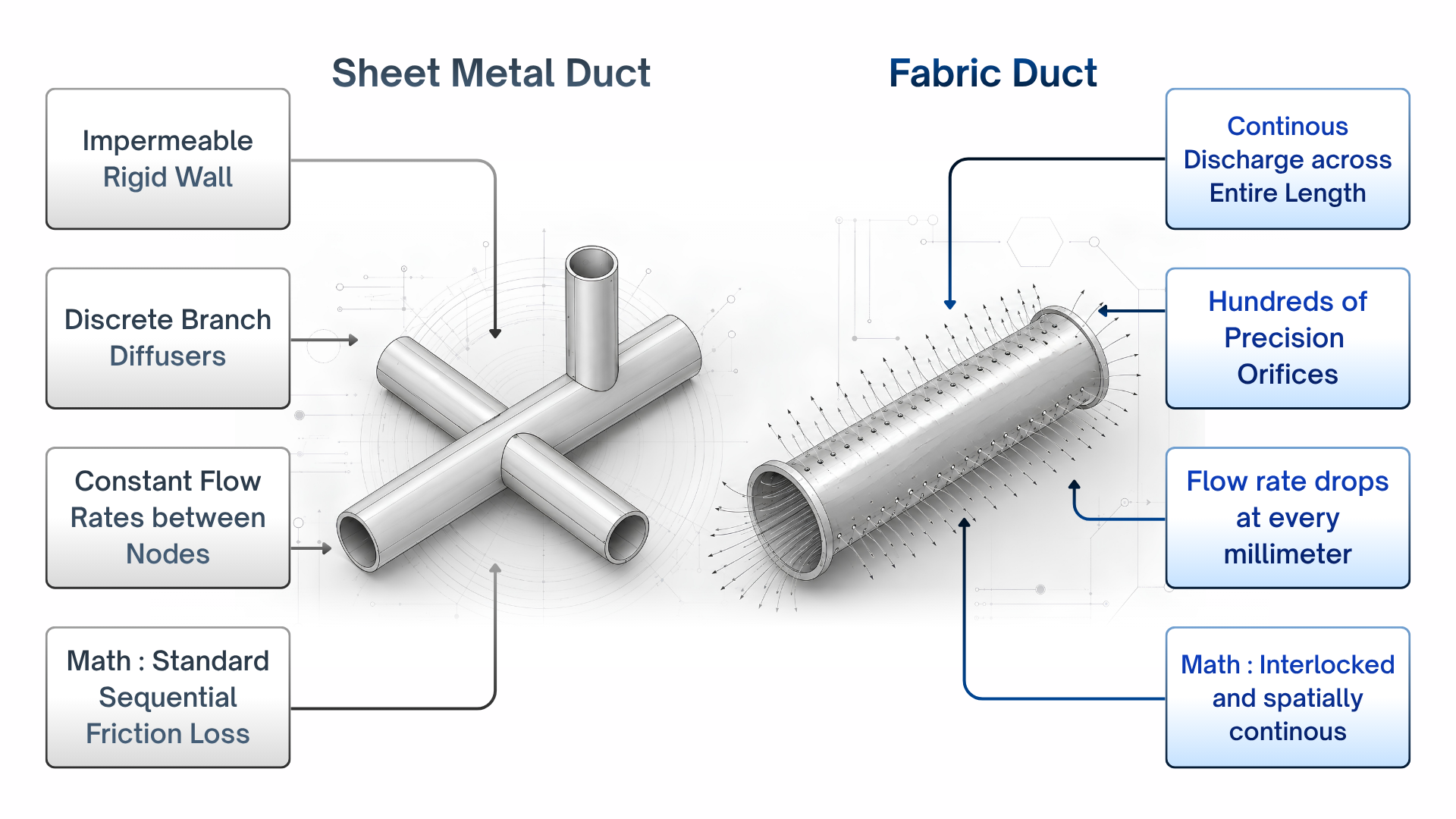
In conventional sheet metal ductwork, the duct wall is impermeable and rigid. Air travels from the supply of plenum to branch outlets that are spaced at defined intervals. Between any two outlets, the flow rate is constant; the velocity is constant, and pressure analysis reduces computing friction loss along a path of fixed length and cross-section.
A fabric duct breaks this assumption entirely. At every cross-section along the duct, a fraction of the remaining air exits through the orifices. Flow rate decreases continuously from inlet to end-cap. This is not a branch-point effect that can be handled by splitting the duct into segments - it is a spatially continuous phenomenon that occurs at every point along the tube.
The consequence is fundamental: if you treat a fabric duct as though it were a GI duct with friction loss only, your pressure calculation is wrong by design. It ignores the continuously varying velocity, which governs both the friction term and the split between static and dynamic pressure at every cross-section.
The practical failure mode is uneven air distribution. Orifices near the inlet face a combination of high velocity pressure and low static pressure: they under-discharge. Orifices near the endcap face low velocity and high static pressure: they over-discharge. The room receives far more air at one end than the other - which is exactly the comfort problem fabric ducts are designed to eliminate.
The crucial difference: in a fabric duct, static pressure might rise along the duct as velocity falls. This is the static-regain effect - and correctly predicting it is the entire point of the distribution analysis.
3. The Physics: Three Interlocked Equations
The pressure distribution inside a fabric duct is governed by three equations that are not independent - they must be solved together.
3.1 Bernoulli's Principle
First, let’s understand what total, static, and velocity or dynamic pressures are. Think of air in a duct like water flowing through a hose. It carries pressure in two forms at once.
Static pressure is the outward push against the duct wall - it's what forces to air out through the orifices.
Velocity pressure is the pressure tied up in the movement itself - it exists only because the air is in motion.
Total pressure is simply the sum of both, and it's what the fan must generate to keep everything moving.
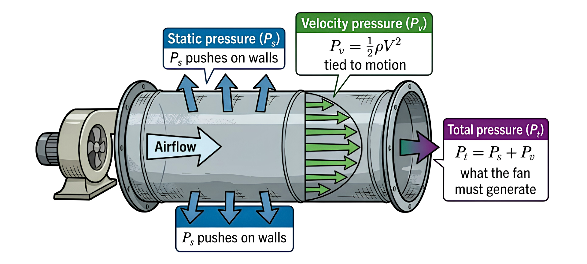
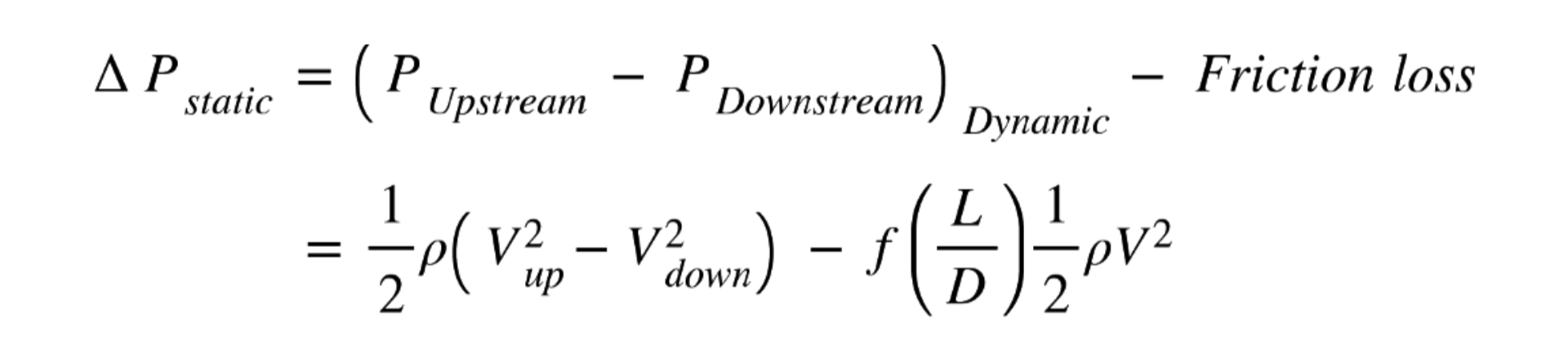
At any cross-section of the duct, total pressure is the sum of static and dynamic (velocity) pressure:

3.2 Static Regain
As air discharges through orifices, the flow rate in the duct decreases. A lower flow rate through the same cross-section means lower velocity, which means lower dynamic pressure. By Bernoulli's principle, the lost dynamic pressure partially reappears as static pressure. This recovery is called static regain.
In a well-designed fabric duct, static regain along each section nearly cancels friction loss - which is why total pressure remains nearly flat, and every orifice sees nearly the same static pressure.
3.3 The Orifice Equation
A precision orifice or perforation in the fabric wall is a well-characterized flow element. The pressure differential across it drives a discharge jet:
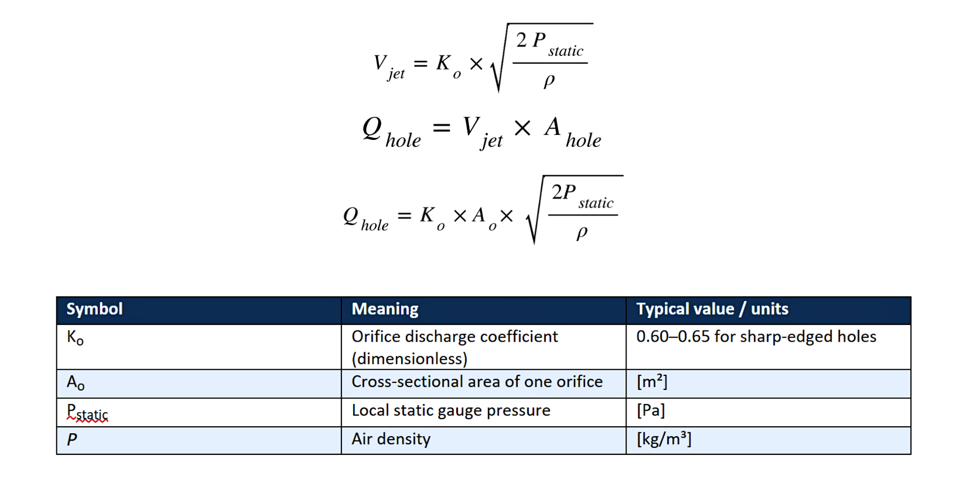
Higher local static pressure leads to a faster jet and more flow per orifice. This is why, when balancing is not done properly, the terminal side orifices over-discharge when static pressure is not carefully managed.
3.4 Why a Coupled ODE Is Necessary
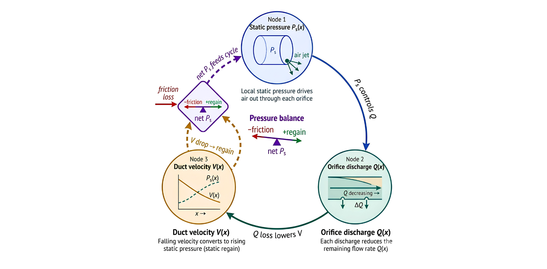
Each quantity feeds into the others simultaneously. The only correct solution is a coupled system of ordinary differential equations - one governing total pressure decay due to friction, one governing velocity decay due to orifice discharge - integrated numerically from the inlet to the end-cap.
KEY INSIGHT
AHC Fabric Duct Design Suite’s, Duct dispersion module solves the ODE solution, which makes it ideal for rigorous fabric duct analysis and overpowers the rule-of-thumb approximations. It captures the feedback between pressure, velocity, and orifice discharge that simpler methods are missing.
AHC Fabric Duct Design Suite’s, Duct dispersion module solves the ODE solution, which makes it ideal for rigorous fabric duct analysis and overpowers the rule-of-thumb approximations. It captures the feedback between pressure, velocity, and orifice discharge that simpler methods are missing.
3.5 Fabric Permeability
Some fabrics allow a distributed seepage to flow through the woven structure itself, independent of any punched orifices. This is characterized by a fabric permeability coefficient Kf [m/(s·Pa)]. For impermeable liners, Kf = 0. AHC Fabric Duct Design Suite models both mechanisms simultaneously within the same coupled ODE framework.
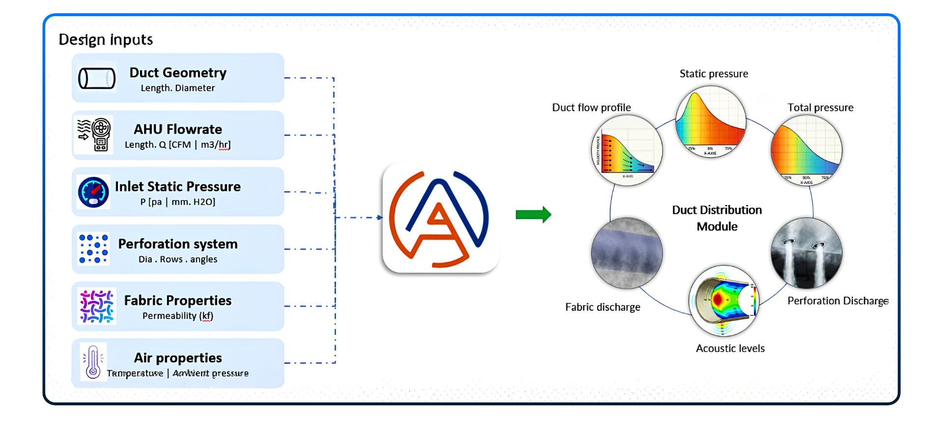
4. AHC Fabric Duct Design Suite - Workflow
When running a distribution analysis in AHC Fabric Duct Design Suite, the engineer specifies the duct geometry and orifice configuration, and the solver computes the full pressure and velocity field.
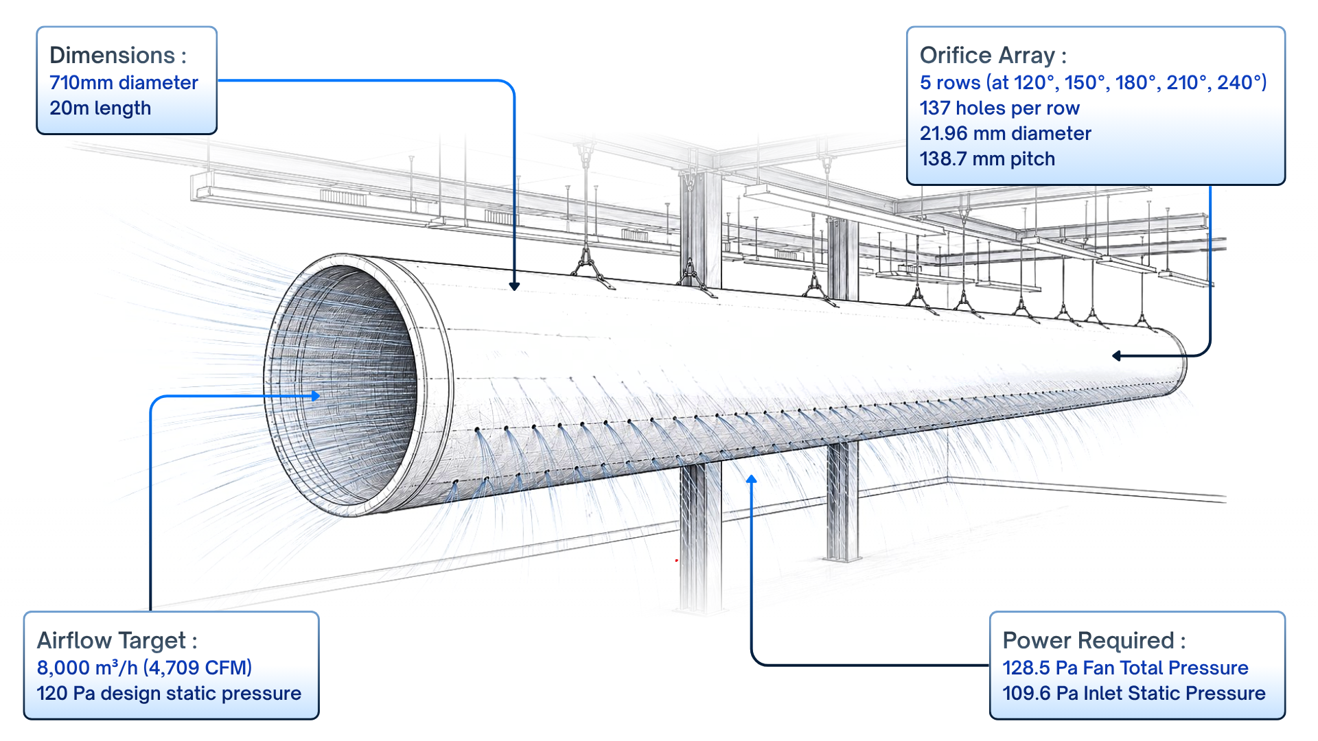
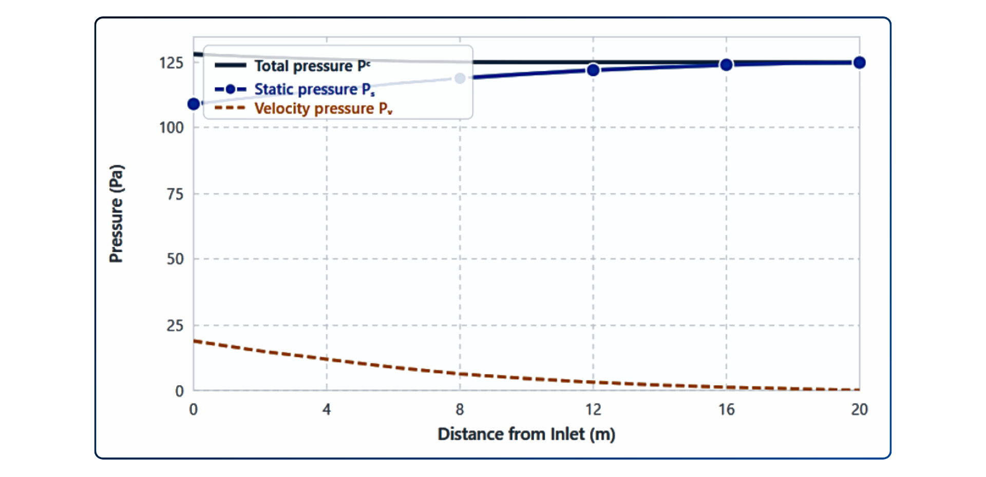
5. Case Study: 20 m straight duct with orifice dispersion
To illustrate the distribution analysis in practice, consider the following design scenario - a single straight circular fabric duct supplying 8000 m³/h into a large open space.
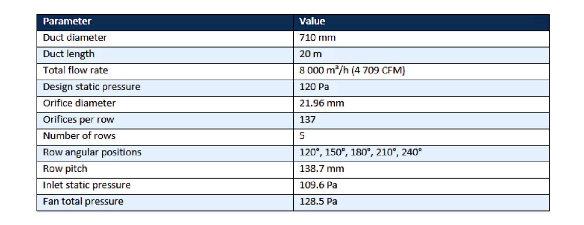
5.1 Results Summary
The static pressure profile rises from 109.4 Pa at the inlet to 125.3 Pa at the end-cap - a 15.9 Pa static regain that confirms near-complete velocity recovery. Total pressure declines by only 3 Pa over 20 m, reflecting how friction-efficient fabric ducts are compared to equivalent metal ductwork.
NOTE ON SENSITIVITY
These results are specific to the given orifice geometry and inlet conditions. Changing the inlet pressure, orifice pitch, or flow rate will shift all profiles. AHC Fabric Duct Design Suite recomputes the full ODE solution whenever any input changes.
These results are specific to the given orifice geometry and inlet conditions. Changing the inlet pressure, orifice pitch, or flow rate will shift all profiles. AHC Fabric Duct Design Suite recomputes the full ODE solution whenever any input changes.
6. Validation with Experimental data
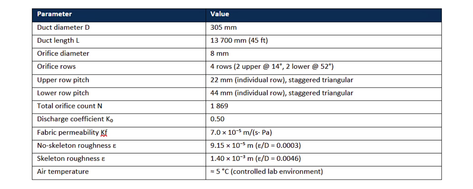
To verify that AHC solves the governing pressure-velocity equations accurately, its predictions were compared against static pressure measurements collected in a controlled HVAC laboratory setting.¹ The test rig consisted of a single straight fabric duct (D = 305 mm, L = 13.7 m) fitted with four rows of precision orifices and a sealed porous end cap, operated across a range of Reynolds numbers representative of typical commercial applications (Re = 123 000-320 000).
Six test conditions were run: three without an internal support skeleton (lower wall roughness, ε = 9.15×10⁻⁵ m) and three with skeleton (ε = 1.40×10⁻³ m). Static pressure was recorded at six axial stations evenly spaced along the duct length. AHC Fabric Duct Design Suite was configured with the same geometry and airflow as each laboratory ran.
Test Rig Parameters
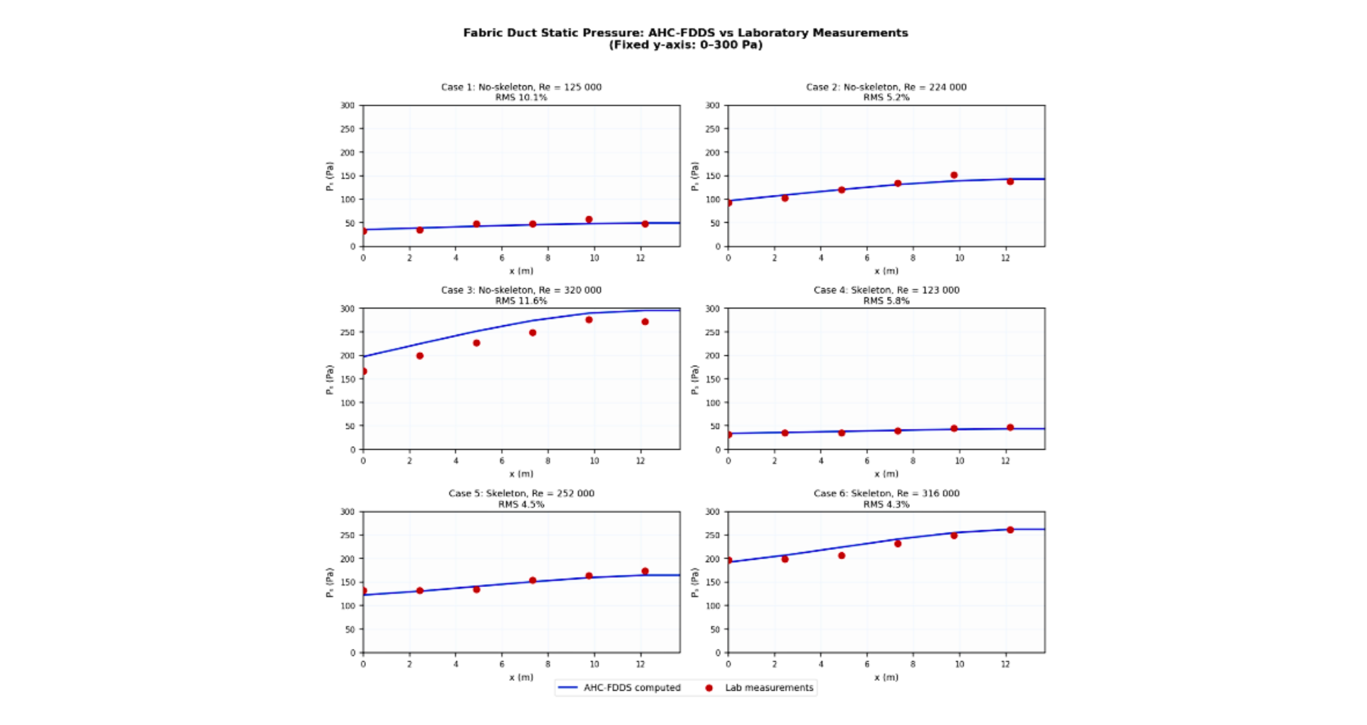
Validation Results Summary
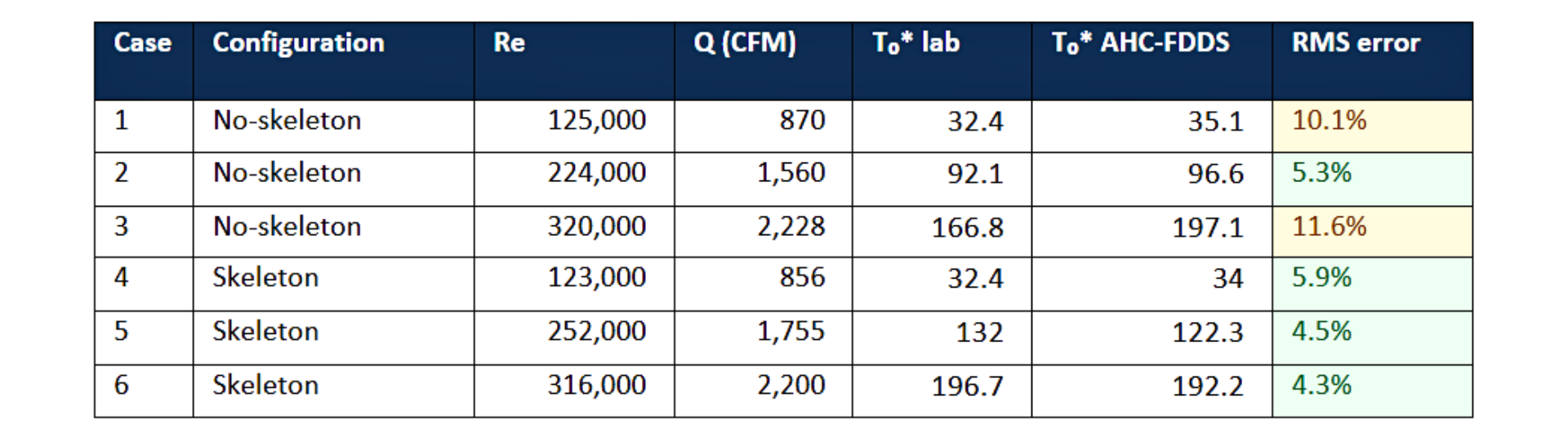
Key Findings
AHC-Fabric reproduced the measured static pressure profiles across all six test conditions with RMS errors ranging from 4.3% to 11.6%. These results confirm that the AHC-Fabric, duct distribution captures the physics of fabric duct air distribution with engineering-grade accuracy.
7. Closing
The key takeaways from this analysis are straightforward, but they have real design consequences:
- AHC Fabric duct pressure distribution cannot be solved with standard duct friction methods - the continuous discharge of couples' velocity, pressure, and orifice flow at every point along the duct length.
- The static-regain effect causes static pressure to rise along a well-designed fabric duct - the opposite of a GI duct. Engineers who apply sheet-metal duct intuition to fabric ducts will over-estimate pressure loss and under-design the orifice geometry.
- AHC Fabric Duct Design Suite, correctly captures all physical mechanisms simultaneously
ABOUT AHC FABRIC DUCT DESIGN SUITE
AHC Fabric Duct Design Suite - part of the simulationHub platform - implements this coupled ODE analysis for single ducts and full branched networks. Distribution analysis is available for both circular and rectangular fabric duct profiles, with or without fabric wall permeability.
Sizing your ducts? The next article covers static-regain duct diameter sizing - how to choose diameters that keep static pressure uniform from inlet to end-cap.
References :
- ASHRAE (2021). Handbook - Fundamentals, Chapter 21: Duct Design.
- ISO 5801:2017. Industrial fans - Performance testing using standardized airways.
As HVAC systems become more performance-driven, traditional approximations are no longer enough. AHC Fabric Duct Design Suite enables engineers to analyze real pressure dynamics, optimize duct behavior, and make better-informed design decisions from the very beginning. Learn more about advanced fabric duct simulation at simulationHub.
Explore the Fabric Duct Design Suite
Book a Free Demo
Comments
Recent posts