Written by Karan Beeshm
Saturday, June 06, 2026
Simulating Cooled Beam HVAC Systems with Buildings AI - Part 2: Sizing, Simulation & Real-World Results
By
Karan Beeshm


Quick Recap
In Part 1, we covered how cooled beam systems work architecturally (hybrid water-air design), the distinction between active and passive beams, and the four empirical equations that govern their thermal performance in Buildings AI. Here in Part 2, we move from theory into practice - how Buildings AI size these systems automatically, what advanced simulation controls are available, and what the numbers look like in real buildings.
For a quick refresher on the fundamentals, visit Part 1 for the full recap.
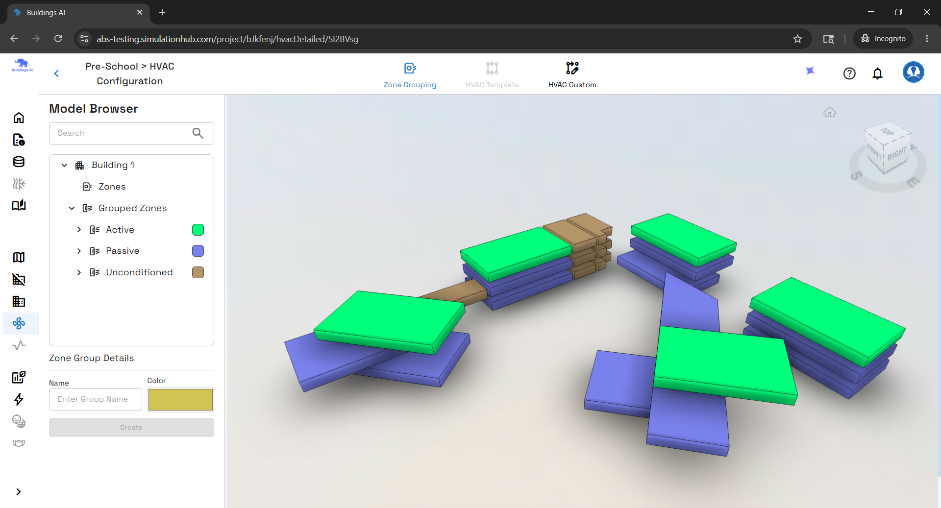
3: System Sizing in Buildings AI
3.1 The Auto size Strategy
One of Buildings AI's most powerful features is automatic cooled beam sizing from design loads. Rather than requiring users to manually guess the number and length of beams (error-prone and tedious), the simulation engine calculates both during the sizing phase. The user provides four inputs:
- Maximum chilled water flow rate available (or allows auto size)
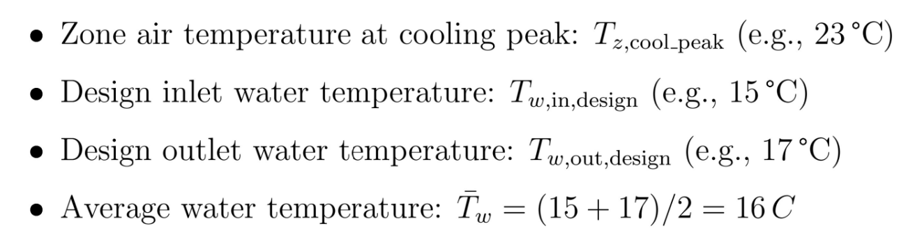
- Design inlet water temperature - typically 15°C
- Design outlet water temperature - typically 17°C
- Supply air flow rate (based on ventilation requirements)
From these, the engine computes how many beams the zone needs and how long each beam must be to meet the design cooling load.
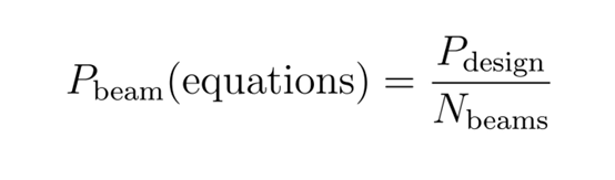
3.2 Number of Beams Calculation

The nominal water flow rate per beam is fixed at 0.07 kg/s by Energy Plus/Buildings AI. For example, if a conference room requires 2.8 kg/s of chilled water flow at peak load:

3.3 Beam Length Calculation
Solving for beam length requires solving the nonlinear performance equations simultaneously across five steps:
Step 1 - Define Design Conditions
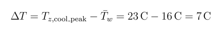
Step 2 - Calculate Average ΔT
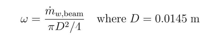
Step 3 - Per-Beam Flow Quantities
Each beam's share of total water and air flow is divided by N_beams. Water velocity ω is then:
Step 4 - Design Cooling Load per Beam
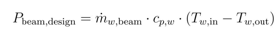
For example, with 0.07 kg/s flow and 2°C rise: P = 0.07 × 4186 × 2 = 586 W/m
Step 5 - Solve for Beam Length
The simulation iterates beam length L until:
For passive beams, this can be solved directly; for active beams, the induction coupling requires iterative numerical methods. A typical office zone might require 4 beams each 2.4 m long.
4: Advanced Simulation Capabilities
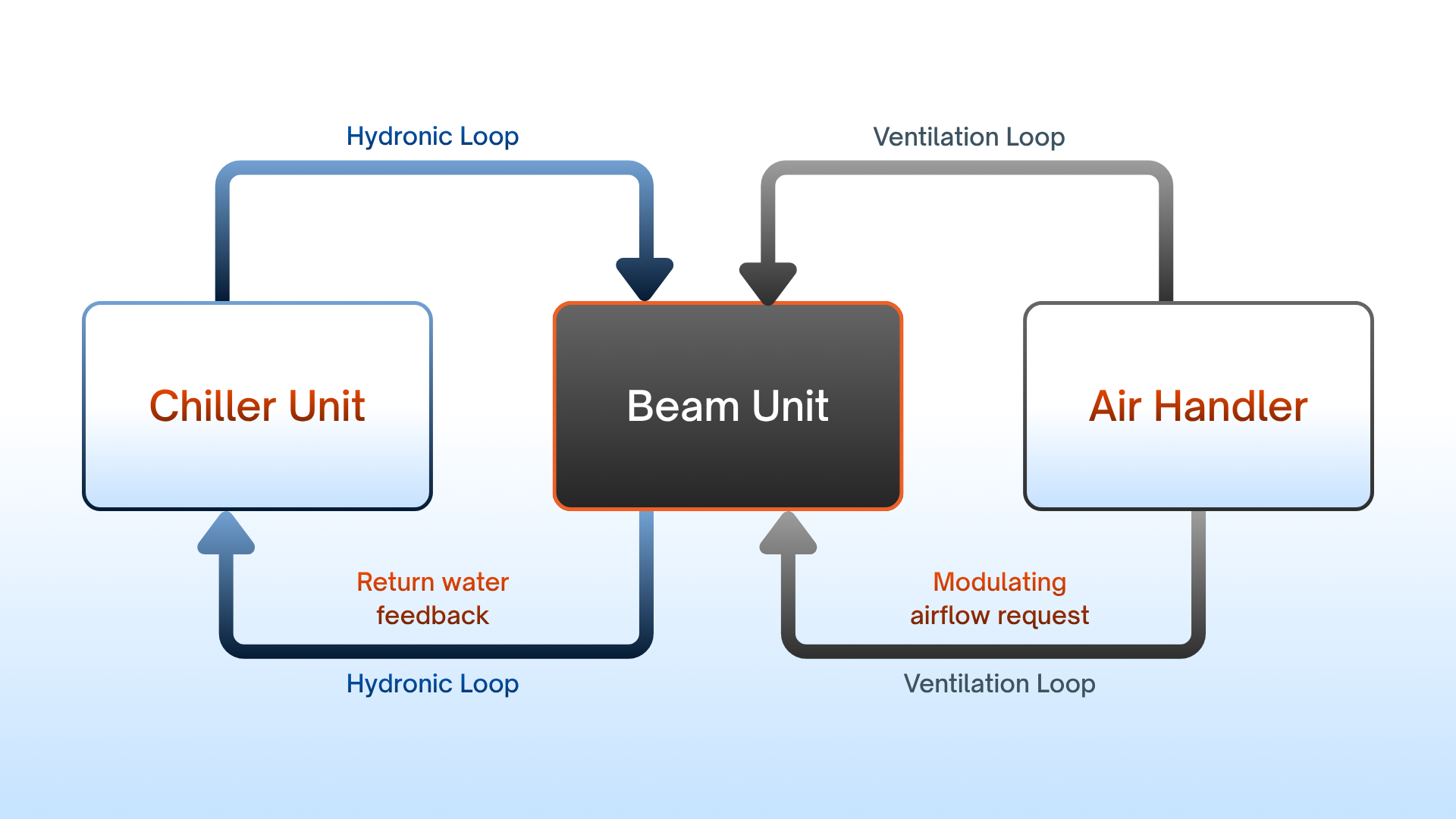
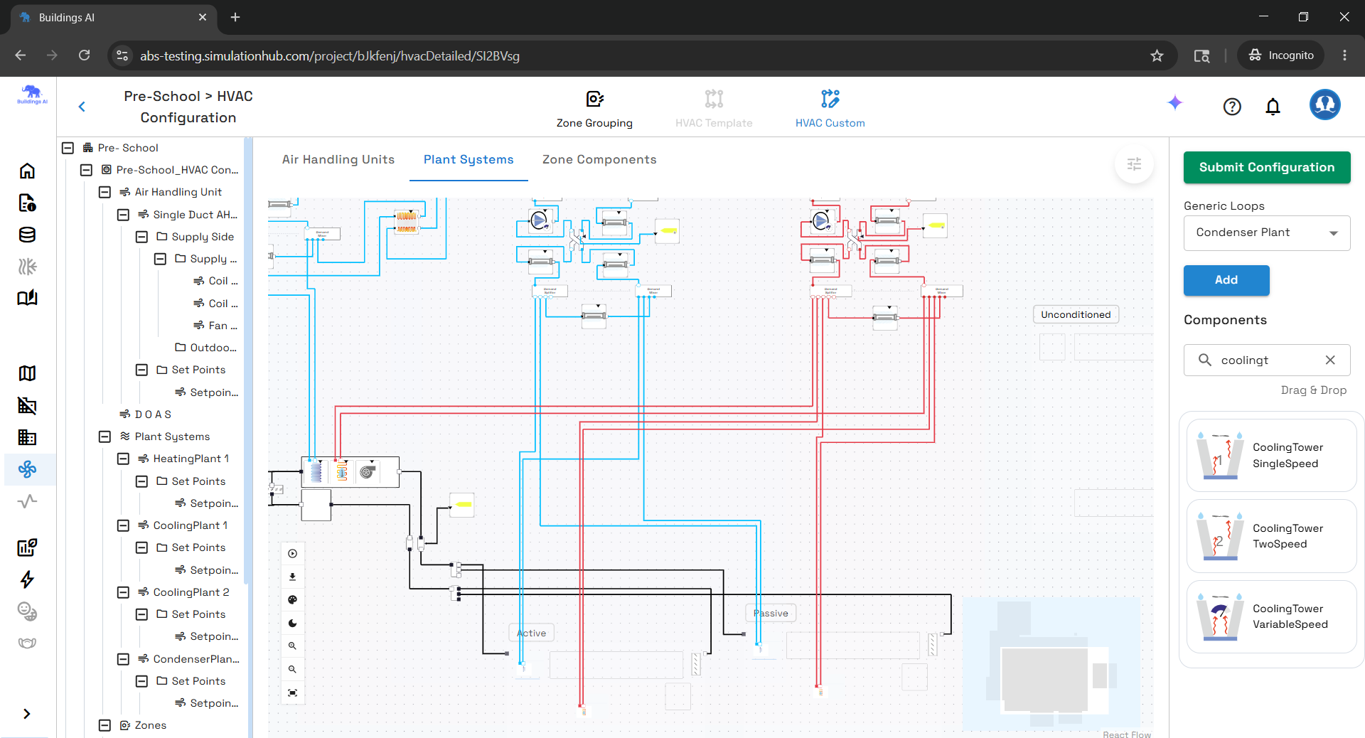
4.1 Integration with the Plant Loop
Buildings AI's cooled beam implementation integrates seamlessly with the full HVAC plant simulation across both fluid loops:
Water Side: Cooled beams connect to a chilled water loop similar to conventional fan coils. The chiller responds to aggregate demand from all zones and returns water temperature feeds back to drive chiller efficiency calculations. Supply water temperature can be controlled globally or locally.
Air Side: Cooled beams act as terminal units on an air loop - modulating airflow in response to controls, mixing room air, and causing the central fan to respond to the aggregate load distribution.
This dual-loop integration captures real physics: how chiller efficiency improves when beams allow warmer water temperatures, how fan energy shifts with changing air volumes, and how supply air temperature resets cascade through zone temperatures.
4.2 Scheduling and Control Flexibility
Users can implement sophisticated control strategies, all evaluated at every simulation timestep:
- Availability schedules - turn off beams during unoccupied periods
- Supply temperature reset - reduce chilled water temperature only when needed
- Demand-controlled ventilation - reduce primary airflow during low occupancy
- Setpoint managers - adjust zone temperature targets by time of day
4.3 Manufacturer-Specific Calibration
A key strength of the Buildings AI approach is the ability to input exact manufacturer parameters: different beam types carry different K_in values; surface area A varies by beam geometry; exponents n₁, n₂, n₃ are calibrated from laboratory testing; and pipe diameter affects water velocity and pressure drop calculations.
This means simulation results are specific to the actual equipment being designed, not generic approximations.
5: Practical Simulation Results and Interpretation
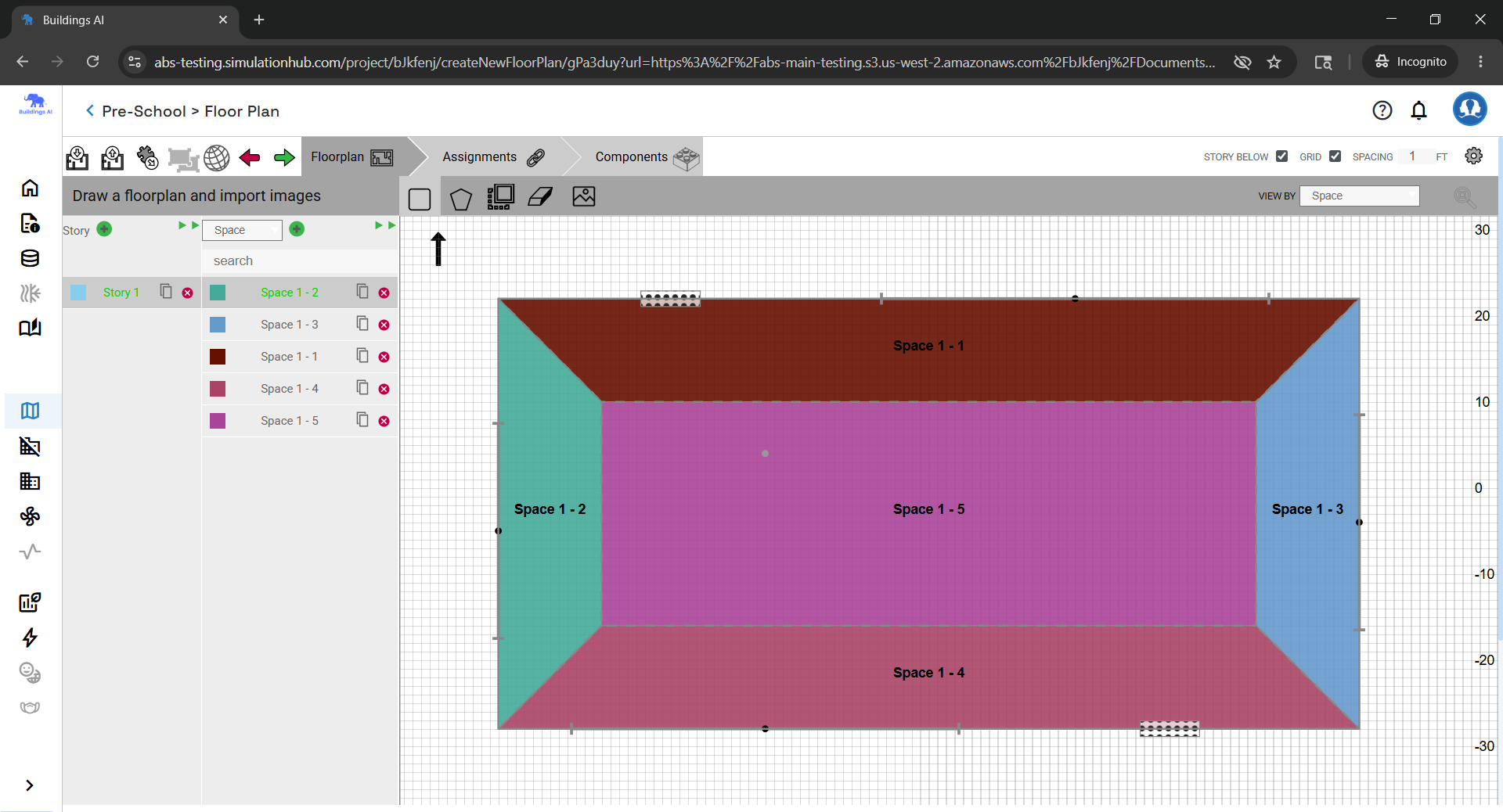
5.1 Case Study: Simple Five-Zone Office Building
Building Profile
A five-zone occupied office facility with a return air plenum. Floor area: 463.6 m² (30.5 m × 15.2 m), floor-to-floor height 3.0 m (0.6 m plenum + 2.4 m occupied). Located in San Francisco (TMYx weather), 30° rotation from north, urban terrain with moderate wind exposure.
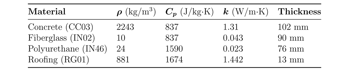
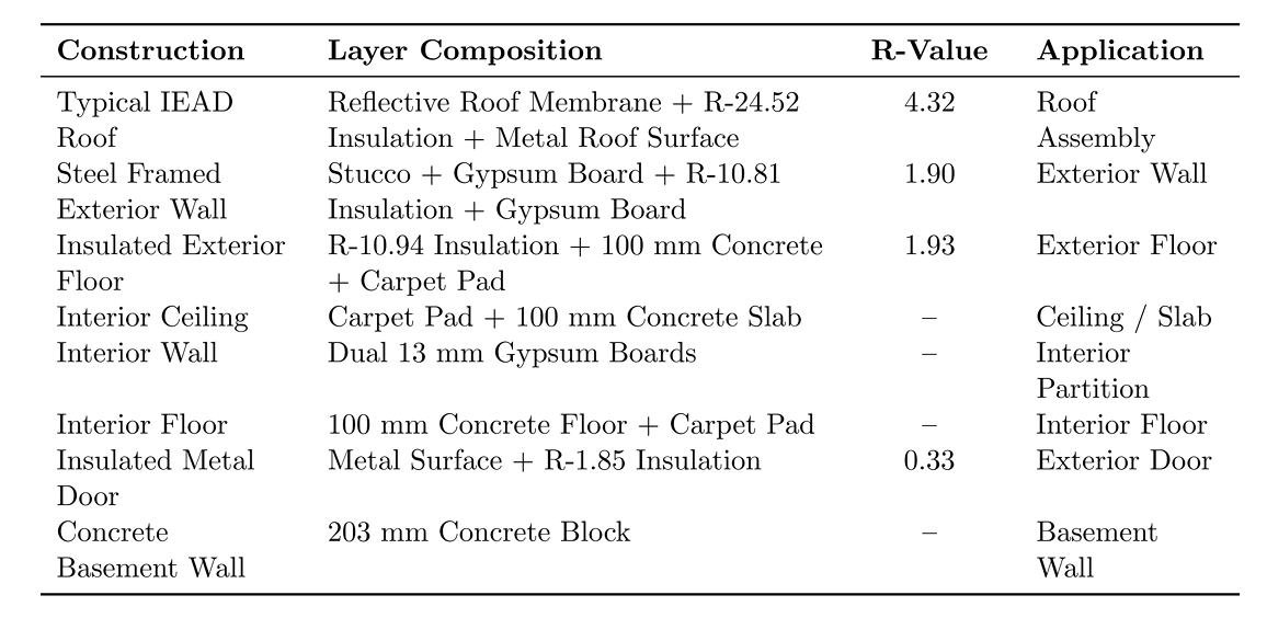
Building Envelope
Table 2 - Building Envelope Specification
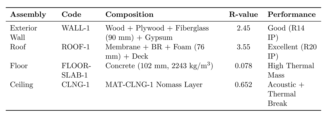
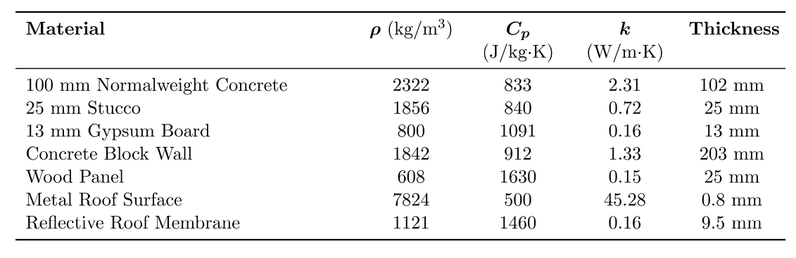
Material Thermal Properties
Windows and Glazing
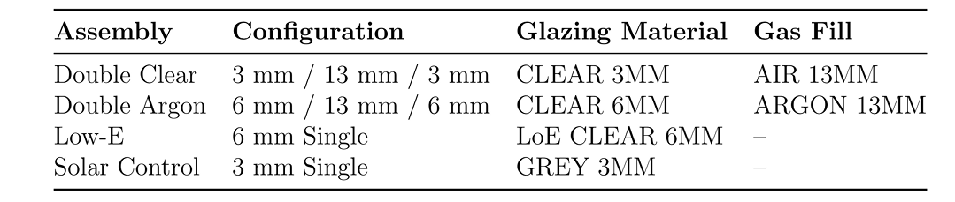
Standard double-clear glazing serves as the baseline for north and west facades. Low-E glazing is recommended for south-facing facades; grey tinted glazing for maximum solar control.
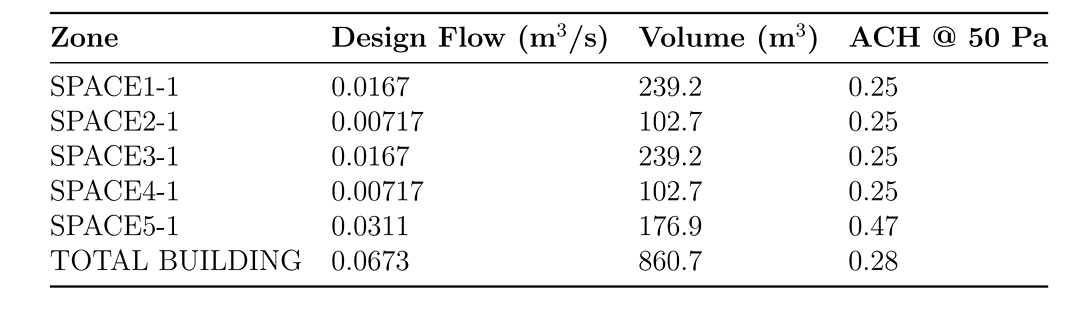
Air Infiltration - Table: Zone Infiltration Rates
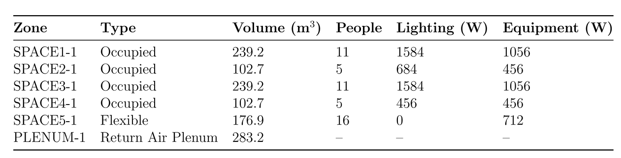
Internal Loads and Occupancy
Table: Internal Loads Summary
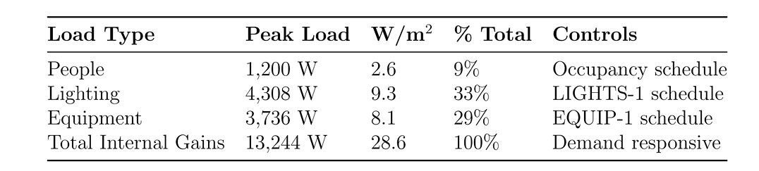
The building accommodates 48 occupants at ~0.10 persons/m². Combined internal gains of ~13 kW dominates cooling demand during occupied periods.
Table: Zone Configuration
This is the equation that ties the whole model together. Room air flow is driven by two mechanisms: natural convection (first term, buoyancy-driven, follows the 0.4 power law characteristic of laminar boundary layers) and air jet induction (second term, directly proportional to primary air supply). For passive beams (Kᵢₙ = 0), only natural convection drives room for air flow.
HVAC System Configuration
The baseline chilled beam system uses a constant-volume 100% outdoor air central ventilation system. The central core zone uses a passive chilled beam; the four perimeter zones use active chilled beam systems with hydronic hot-water baseboard heating for perimeter heat loss.
Central plant: variable-speed pumps, hot-water boiler, electric water-cooled chiller, single-speed cooling tower.
For comparison, the VAV system replaces chilled beam terminals with conventional variable air volume terminal boxes with hot-water reheat. Both systems use identical central plant equipment for a fair comparison.
Energy Performance Comparison - Chilled Beam vs. VAV
Table 3 - Annual Energy Performance Comparison
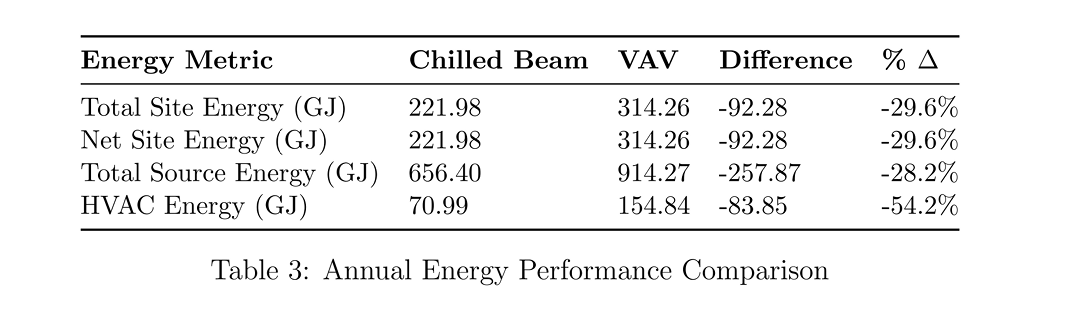
The chilled beam system achieves 29.6% lower annual site energy consumption. The most significant improvement is HVAC energy - reduced by over 54%.
Table 4 - Energy Intensity Performance Metrics
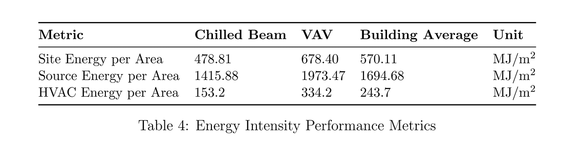
HVAC energy intensity drops from 334.2 MJ/m² (VAV) to 153.2 MJ/m² (chilled beam) - highlighting the efficiency of water-based sensible cooling over air-based distribution.
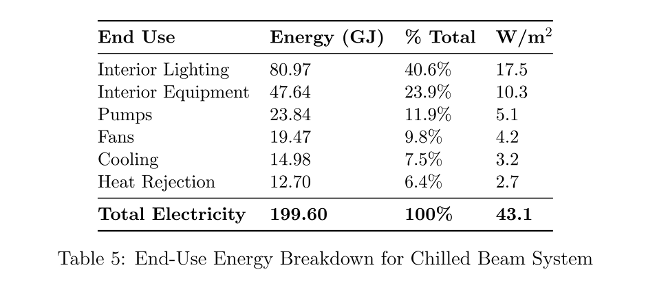
Table 5 - End-Use Energy Breakdown: Chilled Beam System
HVAC energy intensity drops from 334.2 MJ/m² (VAV) to 153.2 MJ/m² (chilled beam) - highlighting the efficiency of water-based sensible cooling over air-based distribution.
Table 6 - End-Use Energy Breakdown: VAV System
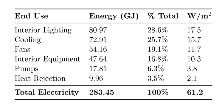
Interior lighting and equipment loads are identical across both systems - confirming the performance difference is entirely driven by HVAC operation. The VAV system cools energy balloons to 72.91 GJ (from 14.98 GJ in the chilled beam system) due to the need to overcool supply air for zone temperature control. While the chilled beam system has slightly higher pump energy (23.84 vs. 17.81 GJ), this is minor compared to fan and cooling savings from hydronic heat transport.
5.2 Case Study: Primary School Building (ASHRAE 90.1)
Building Profile
The second case study extends chilled beam simulation to a real-world primary school developed using ASHRAE 90.1 prototype assumptions. The model includes classrooms, restrooms, circulation spaces, and support areas with occupancy, lighting, equipment, and ventilation schedules representative of educational facilities.
Climate: ASHRAE cooling-dominated assumptions with significant daytime occupancy gains, solar heat gain through fenestration, and dynamic ventilation requirements driven by varying classroom occupancy patterns.
Building Profile
Table 7 - Primary School Building Envelope Specification
Material Thermal Properties
Window Systems
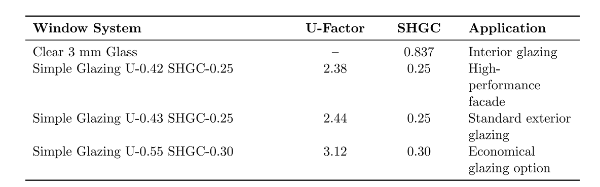
Low SHGC glazing is used throughout to reduce cooling loads while preserving daylight availability for classroom environments.
Air Infiltration and Ventilation

Outdoor ventilation follows ASHRAE 62.1 with occupant-based and area-based airflow rates:
- Outdoor air per person: 0.00472 m³/s-person
- Outdoor air per floor area: 0.00061 m³/s-m²
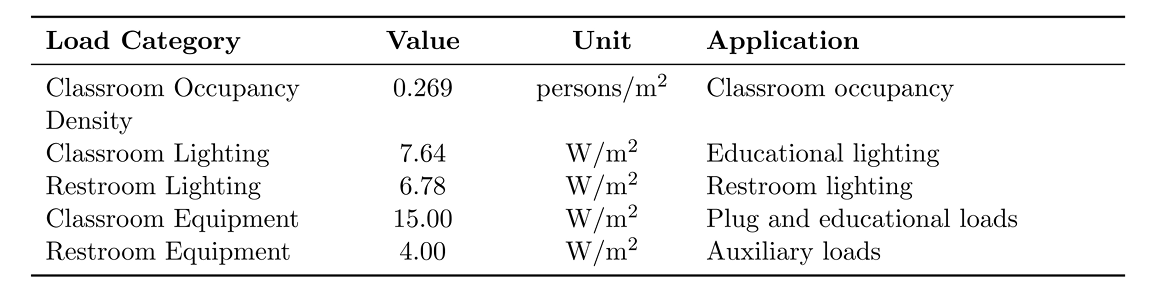
Internal Loads and Occupancy
Table: Internal Loads - Primary School
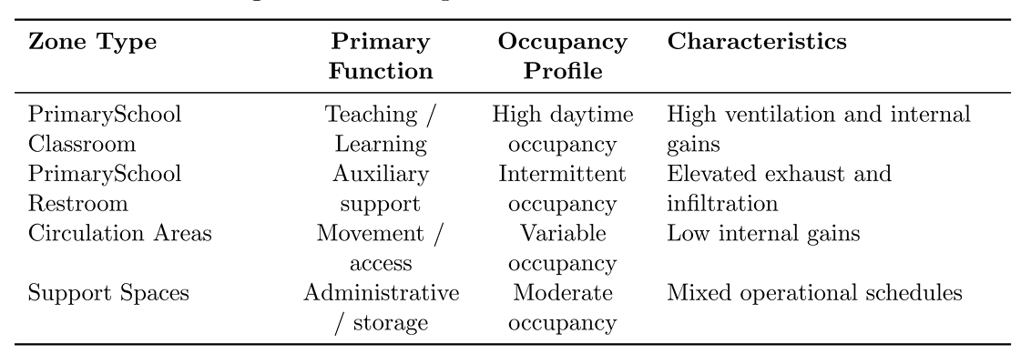
Zone Types
HVAC System Configuration
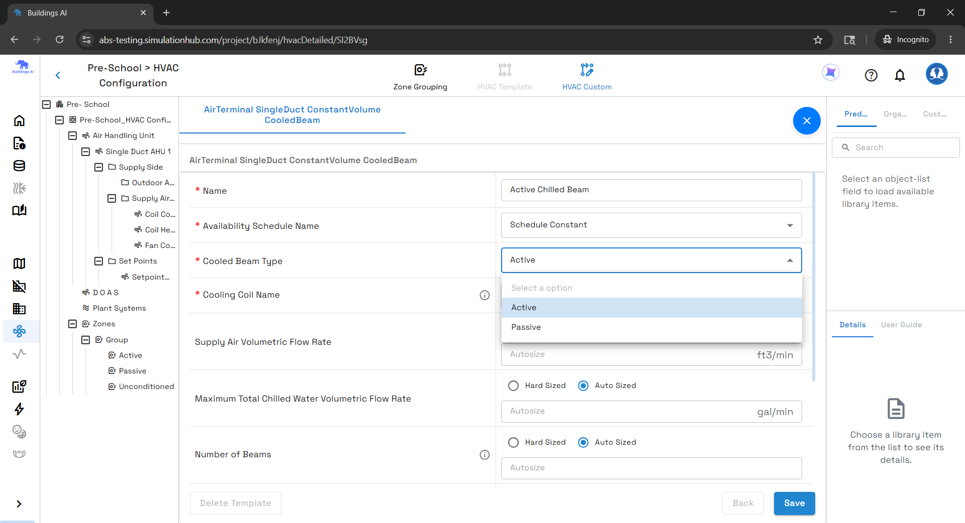
The school uses the same baseline chilled beam architecture: constant-volume 100% outdoor air DOAS, passive beams at the core, active beams at perimeter zones, with hydronic baseboard heating at all occupied perimeter zones.
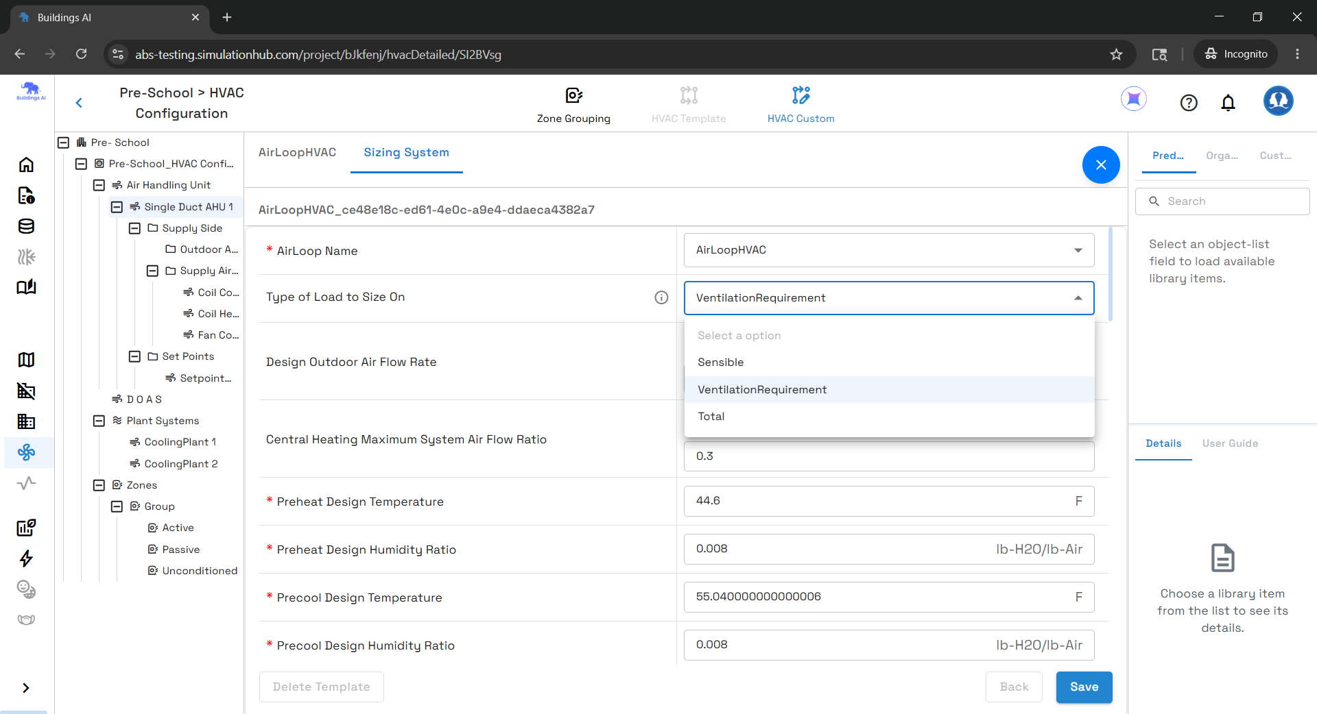
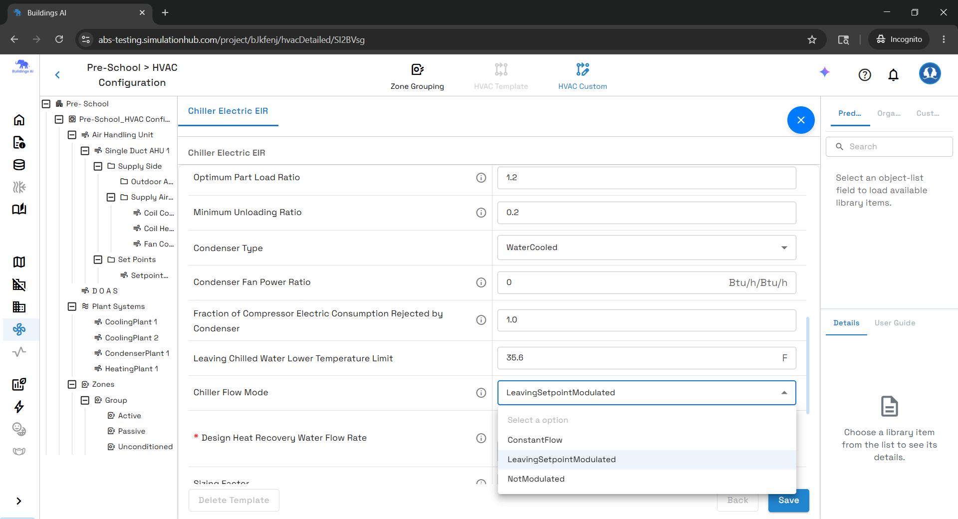
Advanced Control Strategy: The AHU is configured with VentilationRequirement sizing - DOAS airflow is determined by outdoor air ventilation demand rather than zone sensible loads, preventing oversizing the air system. The electric chiller uses LeavingSetpointModulated flow control for dynamic chilled water modulation based on leaving water temperature setpoints.
Chilled Beam System Components and Sizing
Table: Chilled Beam Units - Autosized Results
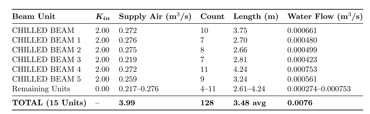
128 chilled beam terminals across 15 conditioned zones. Beam counts range 4-11 per zone; lengths vary 2.61-4.24 m depending on sensible cooling demand. The K_in = 2.0 is maintained across all active beam units to ensure stable entrainment performance.
Table 8 - Hot Water Baseboard Heating Units
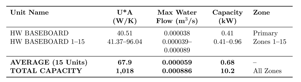
Total installed baseboard heating capacity is 10.2 kW with an aggregate thermal conductance of ~1,018 W/K - providing sufficient redundancy and stable perimeter comfort control.
Central Plant and System Capacity
Table: Central Plant Sizing
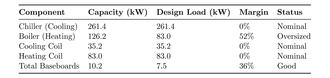
The 261.4 kW water-cooled electric chiller is sized precisely to peak cooling load. The hot water boiler carries a 52% margin above peak heating load - supporting rapid warm-up, perimeter heat compensation, and stable transient winter operation.
Thermal Comfort and Setpoint Performance
ASHRAE guidelines recommend annual occupied unmet load hours below approximately 300 hours. The primary school simulation shows facility-level occupied cooling unmet hours, reaching 429.5 hours annually - slightly above the benchmark, primarily in solar-exposed perimeter zones.
The elevated hours are associated with zoning granularity, solar load distribution, and airflow allocation rather than insufficient plant capacity. Suggested optimization strategies:
- Improved thermal zoning and perimeter segmentation
- Enhanced chilled beam allocation in high solar gain zones
- Dynamic supply air reset strategies
- Additional shading or façade optimization for west- and south-facing spaces
Despite exceeding the comfort benchmark, overall HVAC performance remains reasonably acceptable for an early-stage simulation and demonstrates stable thermal operation across the majority of occupied periods. Heating setpoint violations are minimal, confirming that the hydronic perimeter heating system is adequately sized.
Engineering Interpretation - Key Takeaways
Across both case studies, the results confirm what the physics predicts: cooled beam systems offer a compelling efficiency advantage in cooling-dominated buildings. The primary mechanisms:
- Reduced fan power - lower primary airflow requirements (air handles ventilation only)
- Improved sensible cooling efficiency - hydronic heat transport is far more energy-dense than conditioned air
- Reduced chiller energy - higher allowable chilled water temperatures (15-17°C vs. 4-7°C)
- Lower air-side pressure losses - smaller duct systems with lower static pressure
- Decoupled ventilation and sensible cooling loads - each subsystem is optimized independently
The chilled beam system proves most advantageous in climates with dominant cooling loads and moderate humidity conditions - exactly the profile of office buildings in temperate climates like San Francisco and most ASHRAE cooling-dominated climate zones.
Buildings Ai's simulation framework - combining manufacturer-calibrated empirical equations, automatic sizing, dual-loop plant integration, and flexible control scheduling - gives engineers a high-fidelity tool to evaluate and optimize these systems before a single piece of equipment is specified.
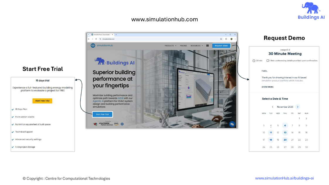
If you want to evaluate chilled beam HVAC performance with accurate autosizing, hydronic loop modeling, DOAS integration, manufacturer-specific calibration, and whole-building energy simulation, Buildings AI can help you move from early design assumptions to data-backed engineering decisions. Visit Buildings AI or request a free demo to see how simulation-ready HVAC workflows can improve comfort, reduce energy use, and build confidence before equipment selection.
Take the Next Step: Start Your Free Trial or Book a Demo
Comments
Recent posts
Message
Dummy Name
Subscribe Newsletter
Register for Webinar
Sign up for AHC
App Dashboard

Buildings AI
Maximize building performance and path towards NZEB with our cloud-based, AI powered whole building performance modeling software.

Autonomous Valve CFD
Get CV, KV performance curves within minutes for your valve design. An automated CFD simulation based app for control valve designers.

Autonomous HVAC CFD
Leverage the power of autonomous HVAC CFD to design an efficient HVAC system for achieving indoor air quality and occupant thermal comfort.