Written by Karan Beeshm
Sunday, May 31, 2026
Simulating Cooled Beam HVAC Systems - Part 1: Understanding the Technology & the Physics
By
Karan Beeshm


Introduction
Cooled beam systems are gaining traction in high-performance building design - and for good reason. Unlike conventional all-air HVAC systems that rely on moving large volumes of conditioned air to handle both ventilation and cooling, cooled beam systems take a hybrid approach: combine a modest central air system for ventilation and dehumidification with hydronic (water-based) ceiling-mounted units that handle the bulk of sensible cooling. The result is a significantly quieter, more energy-efficient, and architecturally flexible climate control solution.
In this two-part series, we explore how Buildings AI - an advanced building simulation platform - accurately models these complex systems, from the underlying physics to real-world case study results.
1 - Understanding Cooled Beam Systems
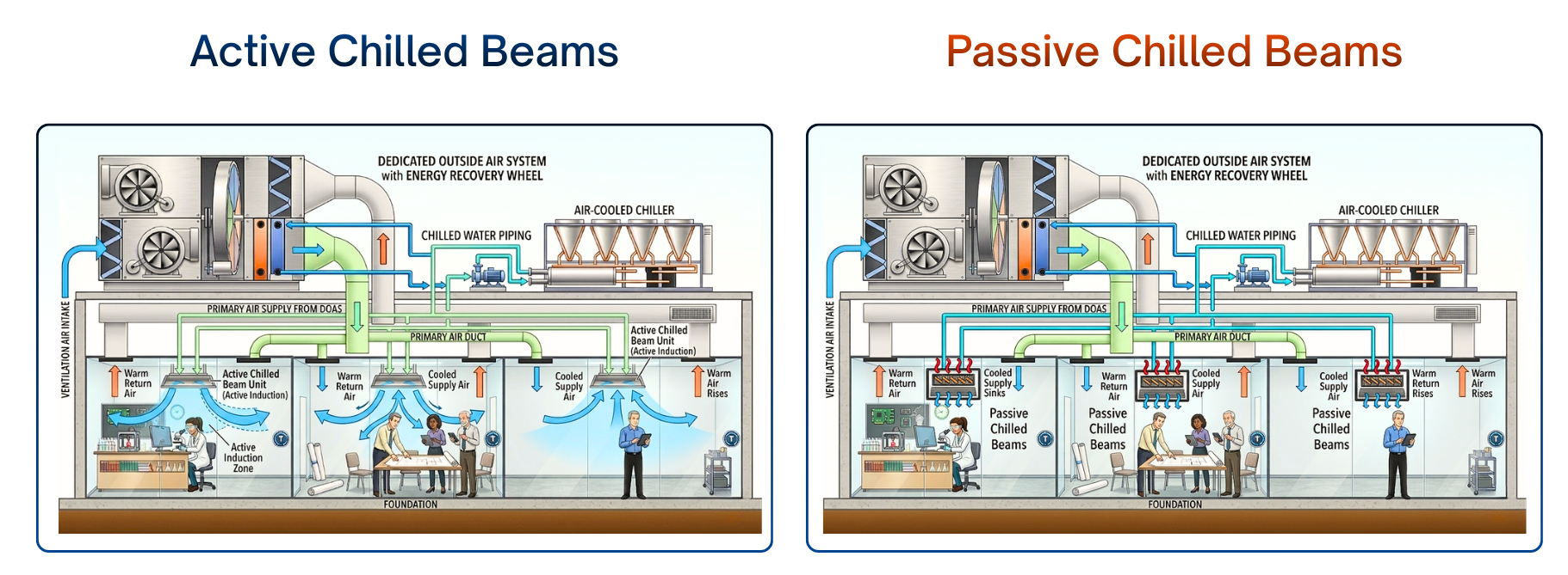
1.1 System Architecture - The Hybrid Approach
A cooled beam system is fundamentally a hybrid water-air HVAC system with two coordinated subsystems working in tandem.
The Central Air System handles ventilation and dehumidification through a constant-volume forced-air network. It includes an outside air mixer, supply fan, heating/cooling coils, and ductwork delivering conditioned air at a fixed supply temperature. Critically, the air volume is sized only for ventilation requirements - not for peak sensible cooling. Its three roles are: meeting fresh air requirements, removing moisture (latent cooling), and contributing partial sensible cooling.
The Chilled Water Distribution System provides the remaining sensible cooling through ceiling-mounted beam units. Key characteristics:
- Chilled water circulates at relatively warm temperatures (15-17°C), compared to conventional systems (4-7°C)
- Water flow rate to each zone is modulated dynamically based on actual cooling demand
- Operates as a 4-pipe system (hot water, cold water, air supply, and air return)
- Ceiling-mounted finned heat exchanger units
Heating is typically handled separately through perimeter baseboards or radiators, keeping it decoupled from the cooling beam design.
1.2 Active vs. Passive Cooled Beams
Buildings AI models both operational modes, each with distinct physical behavior.
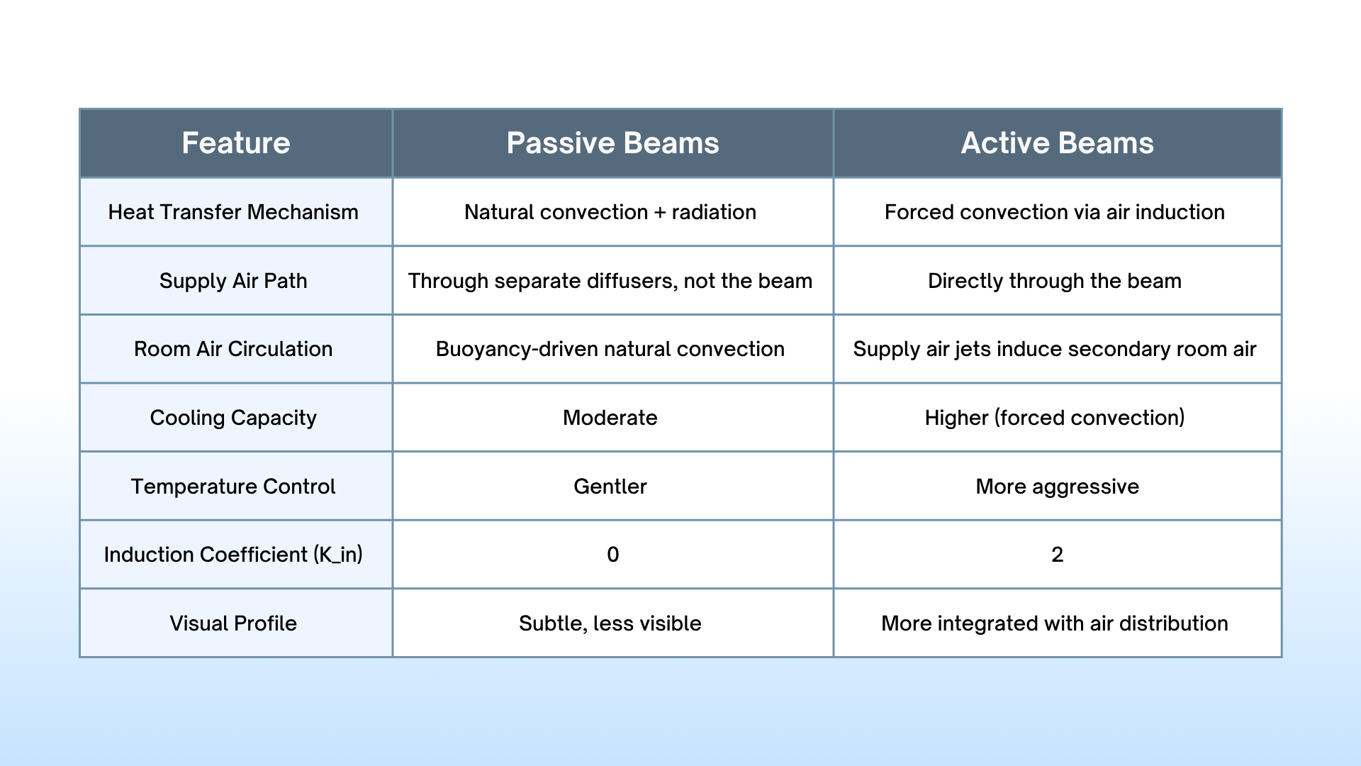
Modeling Note: Both EnergyPlus and Buildings AI model passive and active beams using a convection-only approach - treating even passive beams operating 100% through convection rather than radiation. This conservative simplification remains accurate for the dominant heat transfer mechanism while keeping computation tractable.
1.3 Performance Advantages Over Conventional Systems
Cooled beam systems deliver several compounding advantages over all-air VAV systems:
- Lower water temperatures reduce chiller energy consumption (less mechanical cooling required)
- Reduced fan energy due to lower primary air volumes
- Faster load response through modulated water flow
- Improved thermal comfort - better draft avoidance and more uniform temperature distribution
- Flexible architecture - less ductwork enables more open space planning
2 - The Physics and Mathematics of Cooled Beam Performance
Buildings AI uses an empirical performance model developed by Halton Oy, a leading cooled beam manufacturer. Rather than solving full fluid mechanics and thermodynamics equations from first principles (computationally prohibitive), the model uses curve-fitted relationships that capture essential performance characteristics across the relevant operating range
The model centers on four fundamental equations.
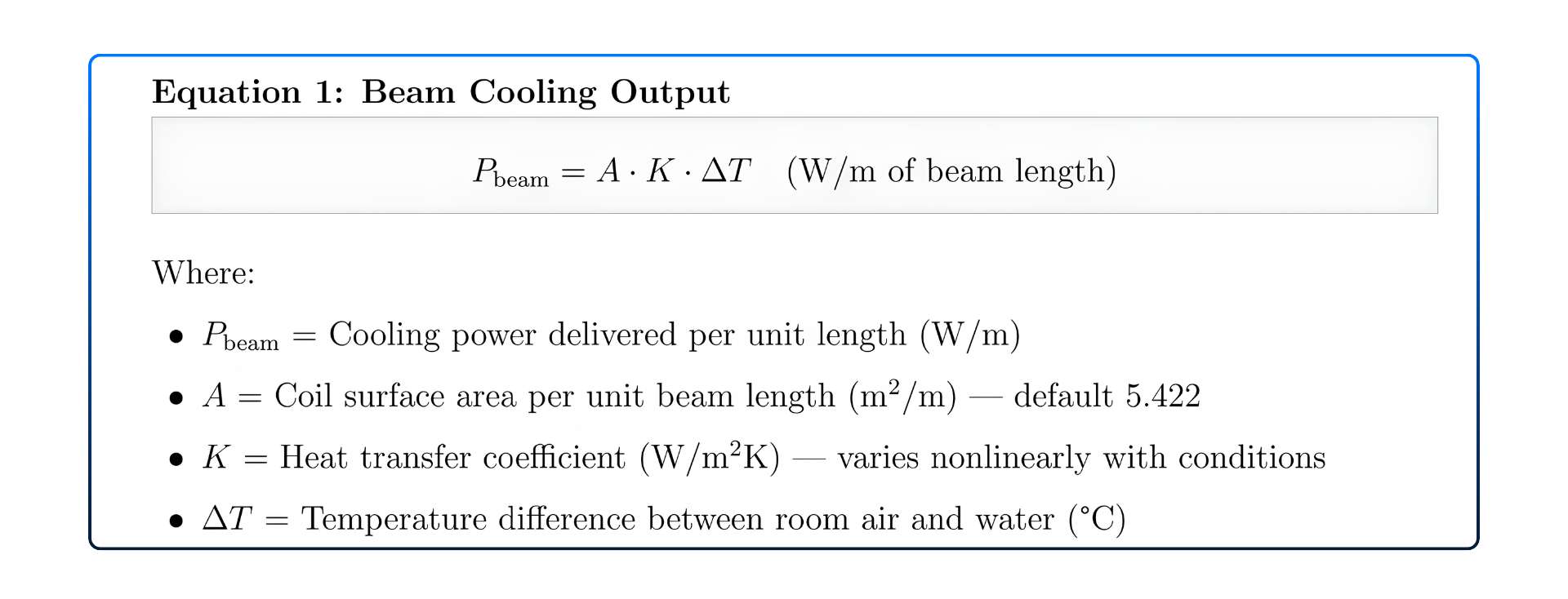
Cooling output scales with three factors - surface area, heat transfer effectiveness, and temperature difference. The elegance lies in how K itself varies with operating conditions.
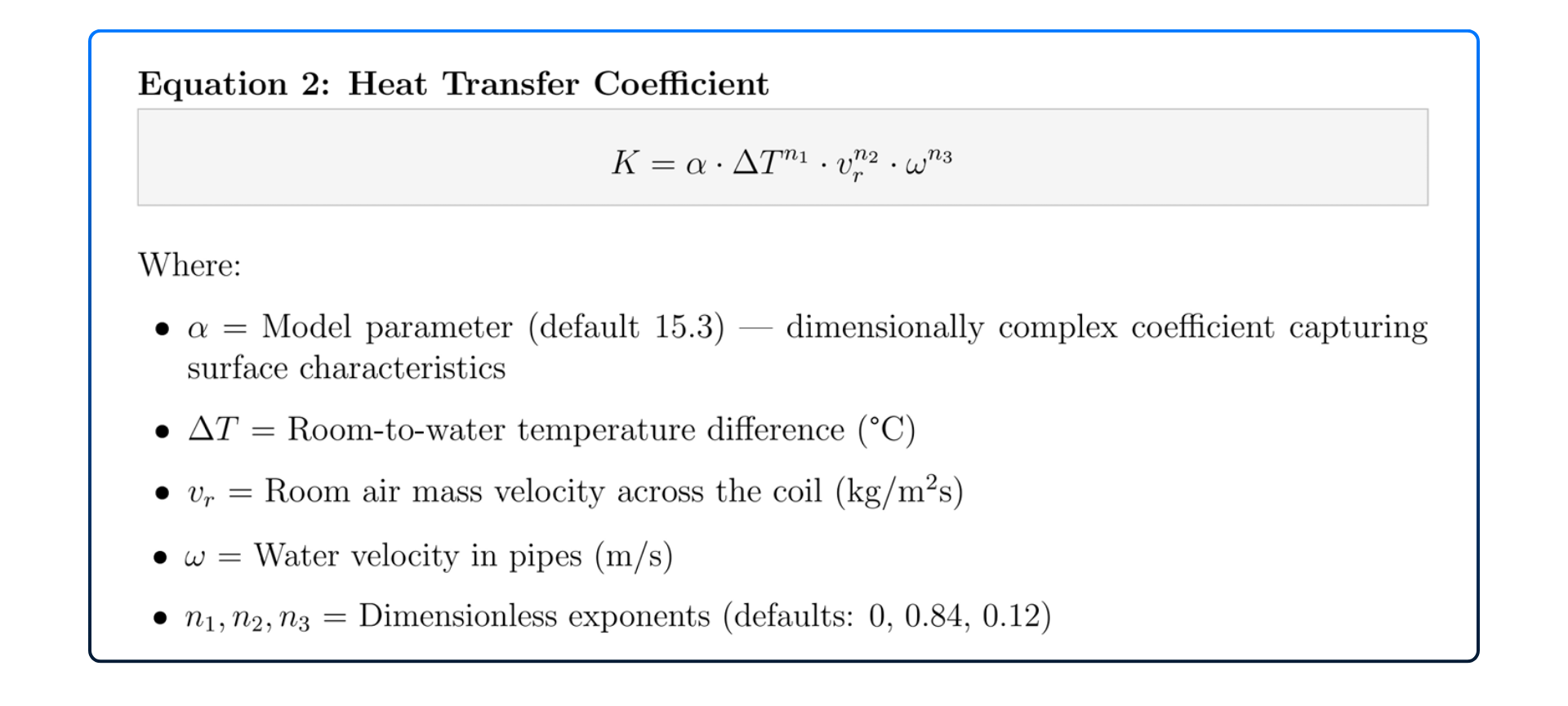
This relationship is nonlinear and highly coupled. n₁ = 0 means K has weak direct dependence on ΔT.
n₂ = 0.84 reflects near-turbulent boundary layer behavior - heat transfer is strongly driven by room air velocity. n₃ = 0.12 indicates moderate water velocity dependence.
n₂ = 0.84 reflects near-turbulent boundary layer behavior - heat transfer is strongly driven by room air velocity. n₃ = 0.12 indicates moderate water velocity dependence.
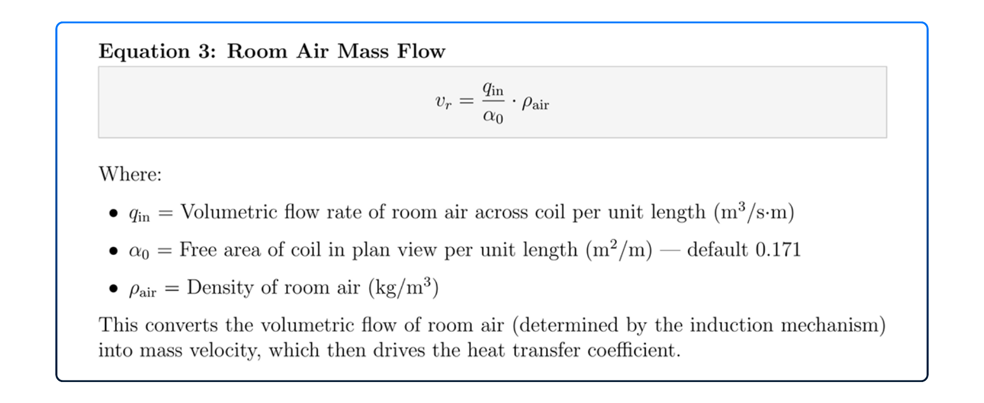
This converts the volumetric flow of room air (determined by the induction mechanism) into the mass velocity that drives the heat transfer coefficient K.
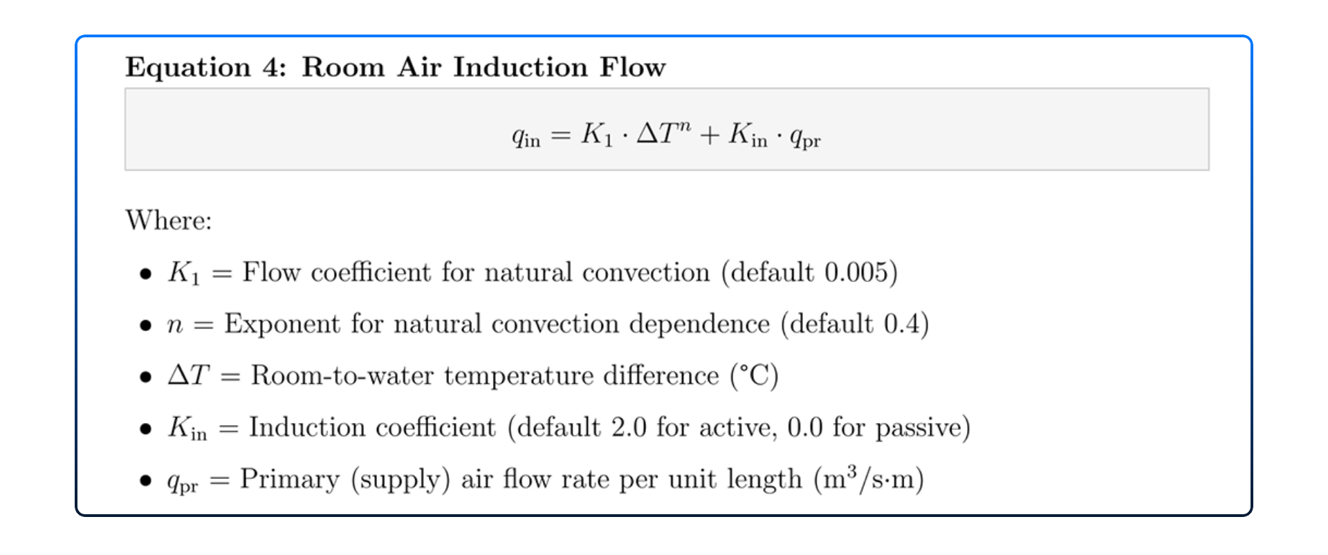
This is the equation that ties the whole model together. Room air flow is driven by two mechanisms: natural convection (first term, buoyancy-driven, follows the 0.4 power law characteristic of laminar boundary layers) and air jet induction (second term, directly proportional to primary air supply). For passive beams (Kᵢₙ = 0), only natural convection drives room for air flow.
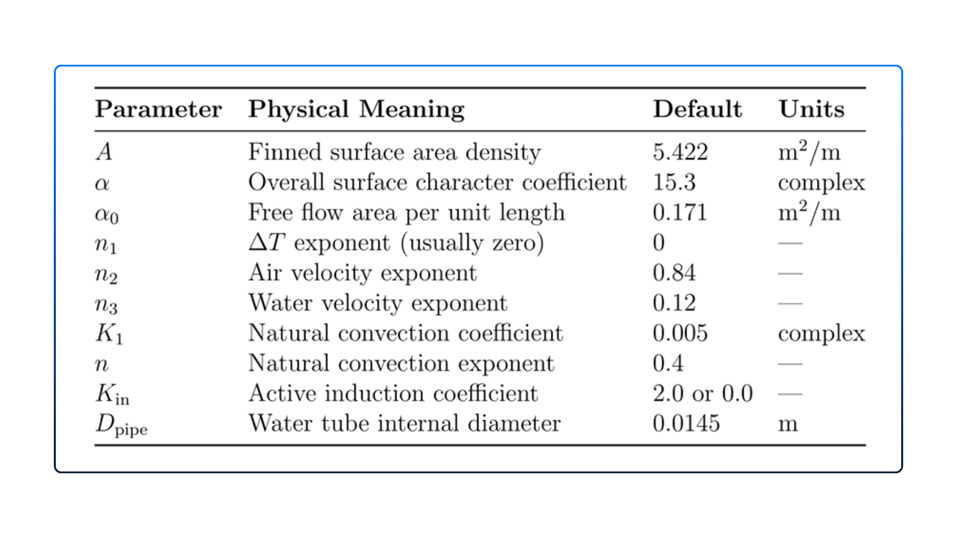
2.2 Parameter Interpretation - Table 1
All model parameters are manufacturer-specific and calibrated from laboratory testing of actual cooled beam units. Buildings AI accepts these as user inputs, enabling simulation of any manufacturer's equipment.
What's Coming in Part 2
Now that we understand what cooled beam systems are and how the physics equations model their behavior, Part 2 gets into the engineering practicalities:
- System Sizing in Buildings AI - how the auto size engine calculates the number of beams and beam length from design loads, step by step with worked examples
- Advanced Simulation Capabilities - plant loop integration, scheduling and control strategies, and manufacturer-specific calibration
- Case Study 1: Five-Zone Office Building - a head-to-head energy comparison between a chilled beam system and a conventional VAV system, with full results tables showing 29.6% total site energy savings and 54.2% HVAC energy reduction
- Case Study 2: Primary School (ASHRAE 90.1) - a real-world multi-zone educational building with complex occupancy patterns, showing how Buildings AI handles ventilation-driven sizing and perimeter heating
If you're an engineer evaluating cooled beam systems for your next project, Part 2 is where the numbers get real.
Take the Next Step: Start Your Free Trial or Book a Demo

Comments
Recent posts
Message
Dummy Name
Subscribe Newsletter
Register for Webinar
Sign up for AHC
App Dashboard

Buildings AI
Maximize building performance and path towards NZEB with our cloud-based, AI powered whole building performance modeling software.

Autonomous Valve CFD
Get CV, KV performance curves within minutes for your valve design. An automated CFD simulation based app for control valve designers.

Autonomous HVAC CFD
Leverage the power of autonomous HVAC CFD to design an efficient HVAC system for achieving indoor air quality and occupant thermal comfort.